
This topic is the install guide for the after-market gateway (part# G0097460) with the universal harness (part# A0006648426) when utilizing Generac Power Zone Pro® or Power Zone Pro Sync using the RS485 port.
Generac Power Zone Pro
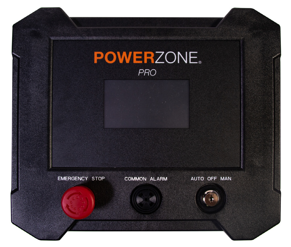
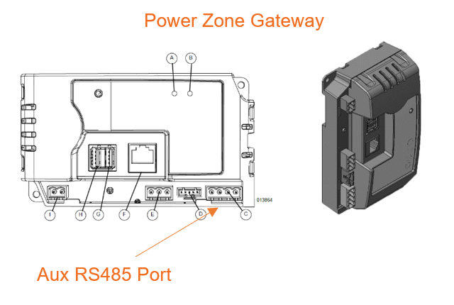
Modbus Communication Settings and Notes
Modbus connection to be made at the Aux RS485 port on the Power Zone Gateway (see image in previous section). Terminal block included in harness accessory kit if needed. To make changes to serial port, key switch must be in Off position.
To confirm the port settings in this table, follow the steps in this section.
|
Serial Port: RS485 Built In |
Parity: None |
|
Unit ID: 1 |
Stop Bits: 1 |
|
Baud rate: 9600 |
Mode: Modbus Gateway |
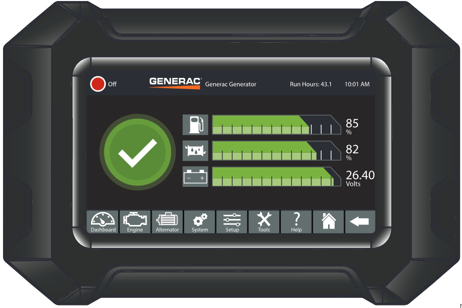
For firmware version 1.21.9 and prior: Navigate to setup > Communications > Modbus Pass Thru. Modbus RTU Enable toggle must be selected and settings should match values provided in the table in this section.
For firmware version 1.22.1 or newer: Navigate to setup > Communications > External Interfaces > Configure > RS485 Built In. Confirm that settings match values provided in the table in this section.
If different settings are required, please contact Support.
It is recommended that firmware is updated to 1.23.2 or higher. An issue was identified with the Modbus RS485 port communications in previous versions.
Equipment Connection Details
Generac Gateway Side Terminations
|
Description
|
Harness Wire Color
|
Equipment Side Terminations
|
|---|---|---|---|
|
+ |
DC+ |
Red |
B+ |
|
- |
DC- |
Black |
B- |
|
A2 |
Data + |
Blue / White |
A-12 |
|
B2 |
Data - |
White / Blue |
B-14 |
|
GND |
Data GND |
White / Green |
SCR-11 |
|
Harness Relay #1 |
COM |
Blue |
2-Wire Start
|
|
N/O |
White / Blue |
Generac Power Zone Pro Sync
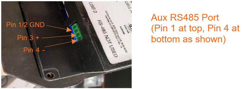
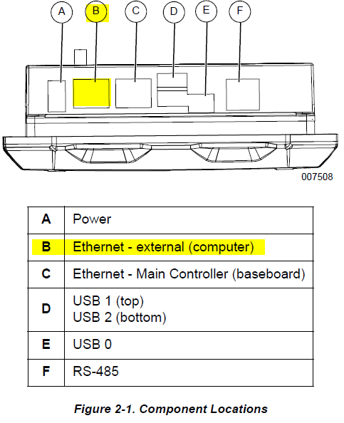
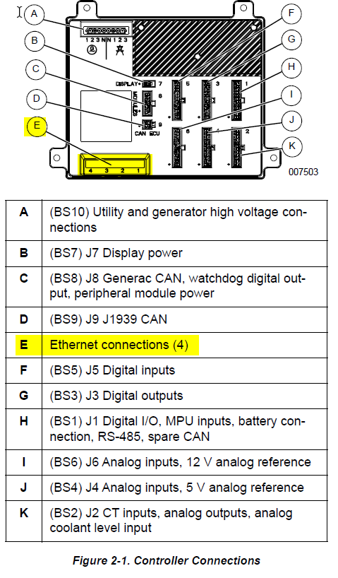
Modbus Communication Settings and Notes:
Modbus connections to be terminated at RS485 port on display. See section above for Power Zone Pro Sync expected settings and programming instructions.
Equipment Connection Details
Generac Gateway Side Terminations
|
Description
|
Harness Wire Color
|
Equipment Side Terminations
|
|---|---|---|---|
|
+ |
DC+ |
Red |
B+ |
|
- |
DC- |
Black |
B- |
|
A2 |
Data + |
Blue / White |
3—RS485+ |
|
B2 |
Data - |
White / Blue |
4—RS485- |
|
GND |
Data GND |
White / Green |
2—GND |
|
Harness Relay #1 |
COM |
Blue |
2-Wire Start
|
|
N/O |
White / Blue |
Gateway Connection Ports
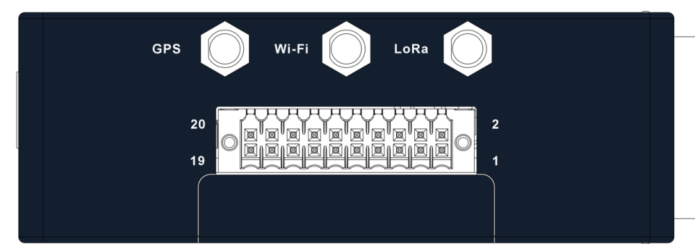
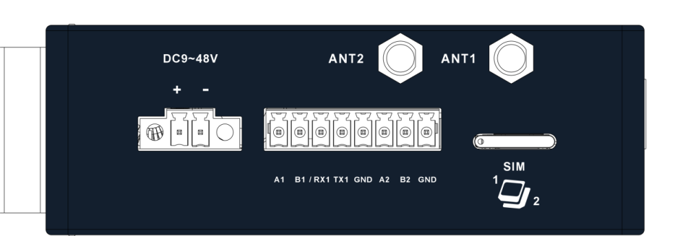
Check out our knowledge base and support center for information on any technical questions.