
This topic is the install guide for the after-market gateway (part# G0097460) with the universal harness (part# A0006648426) utilizing the Generac PowerZone® 410 Controller.
Modbus Communication Settings and Notes
Settings should correspond to the values provided in this table.
|
Address: 157 |
Data Bit: 8 |
|
Baud Rate: 9600 |
Stop Bit: 1 |
|
Parity: None |
|
If different settings are required, please contact Support.
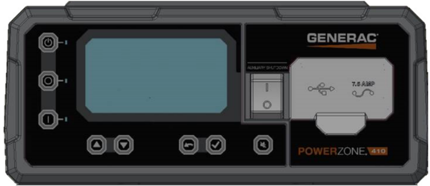
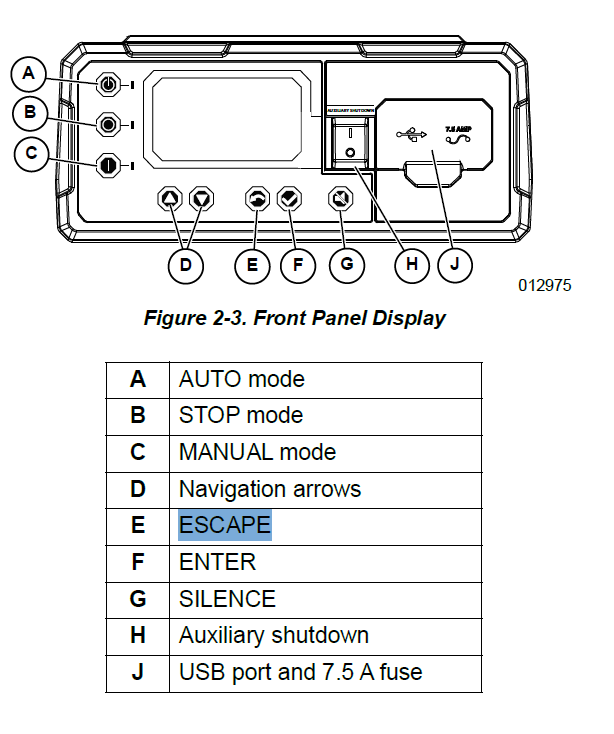
From the control panel as depicted in the schematic in this section, follow the steps provided here.
-
RS485 slave port configuration can be reached through Dealer Menu by entering the Dealer Code.
-
Edit Settings>Config RS485 Slave.
Equipment Connection Details
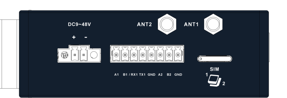
Generac Gateway Side Terminations
|
Description
|
Harness Wire Color
|
Equipment Side Terminations
|
|---|---|---|---|
|
+ |
DC+ |
Red |
B+ |
|
- |
DC- |
Black |
B- |
|
A2 |
Data + |
Blue / White |
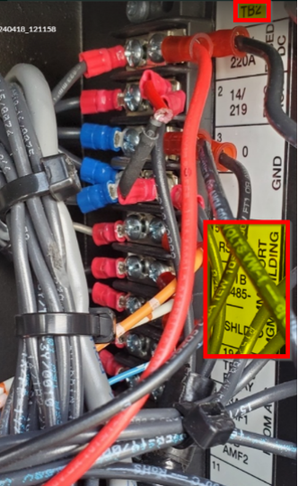
TB2—RS485+ |
|
B2 |
Data - |
White / Blue |
TB2—RS485- |
|
GND |
Data GND |
White / Green |
TB2—SHLD |
|
Harness Relay #1 |
COM |
Blue |
2-Wire Start |
|
N/O |
White / Blue |
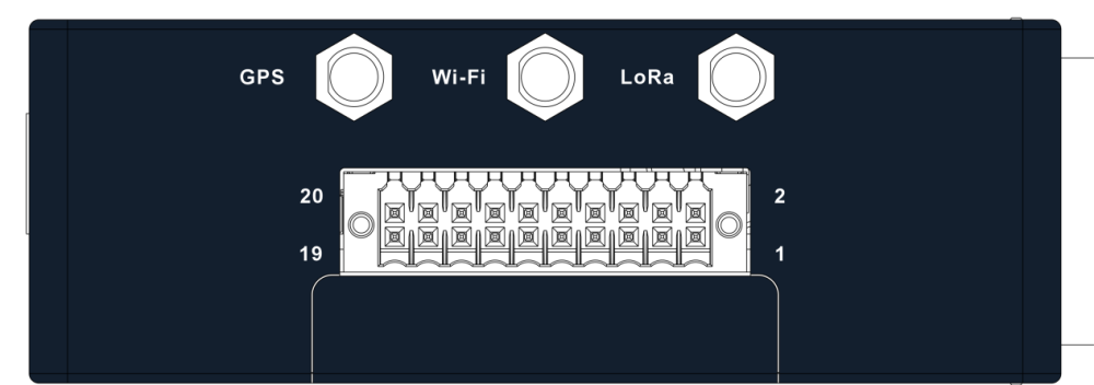
Gateway Connection Ports
Check out our knowledge base and support center for information on any technical questions.