
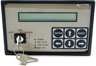
This topic is the install guide for the after-market gateway (part# G0097460) with the universal harness (part# A0006648426) utilizing the Generac E Panel.
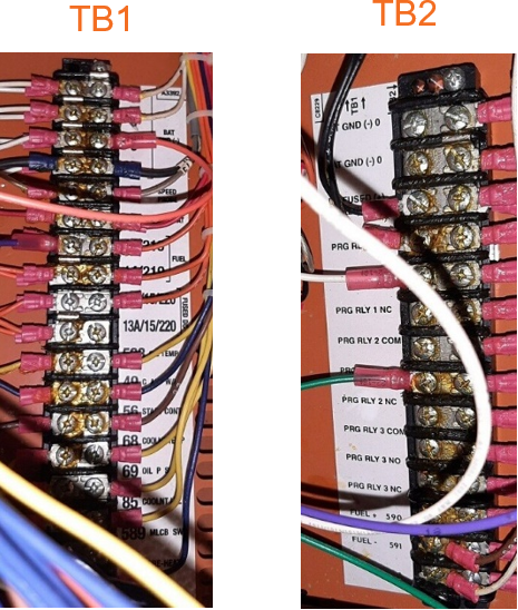
Equipment Connection Details
Generac Gateway Side Terminations
|
Description |
Harness Wire Color |
Equipment Side Terminations
|
|---|---|---|---|
|
+ |
DC+ |
Red |
TB2-3 |
|
- |
DC- |
Black |
Any of TB2-1,TB2-2, or TB1-1 thru TB1-4 |
|
Pin 15 |
Engine Running |
Purple |
TB1-10
|
|
Pin 16 |
Not in Auto |
Green |
*TB2-PRG RLY 2 NC
TB2-PRG RLY 2 COM) |
|
Pin 17 |
Common Alarm |
White |
*TB2-PRG RLY 1 NO
TB2-PRG RLY 1 COM) |
|
Harness Relay #1 |
COM |
Blue |
TB1-178 |
|
N/O |
White / Blue |
TB1-183 |
*TB2 Programmable output relays need to be programmed via front interface. Output Relay 1 should be programmed for “In Auto” (Output Function ID 40) and Output Relay 2 should be programmed for “Common Alarm” (Output Function ID 01).
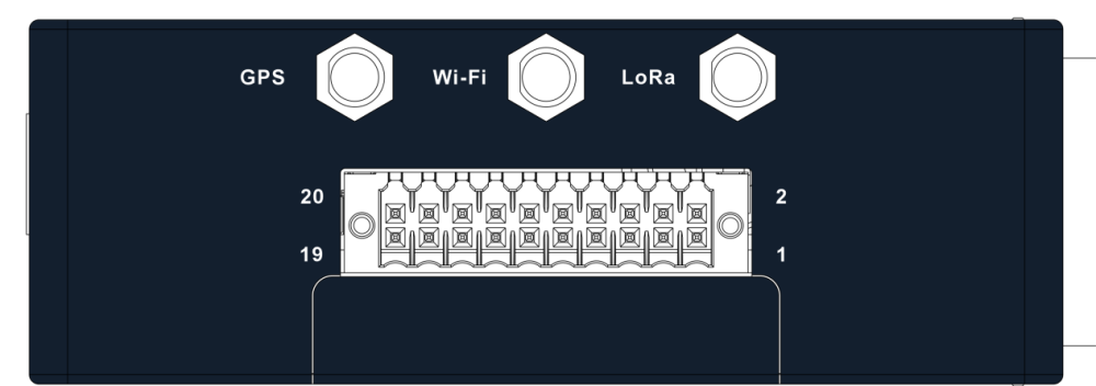
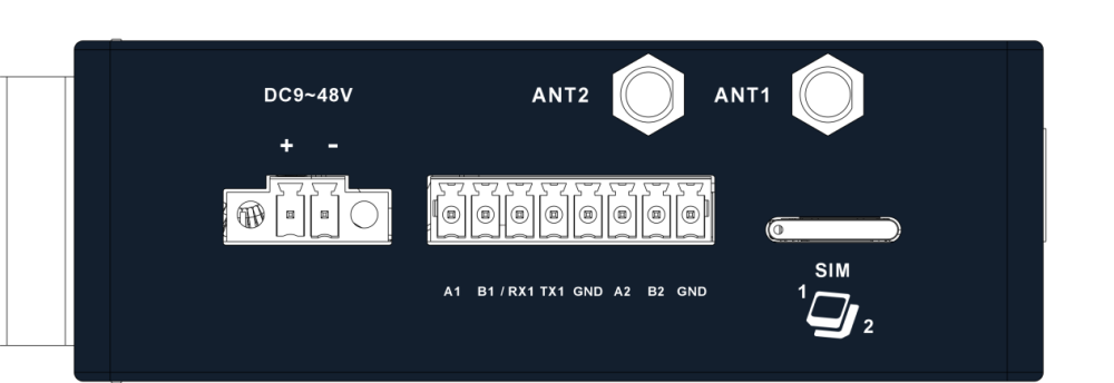
Gateway Connection Ports
Check out our knowledge base and support center for information on any technical questions.