
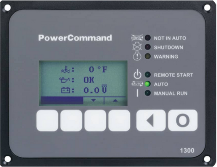
This topic is the install guide for the after-market gateway (part# G0097460) with the universal harness (part# A0006648426) when utilizing Cummins PCC 1.X (1302) PowerCommand® control systems.
Generac Link-Site Deployment Controller Selection:
Cummins PCC 1.X-RS485
Modbus Communication Settings and Notes
Settings should match values provided in this table.
|
Enabled: On |
|
Address: 1 |
|
Baud Rate: 19200 |
|
Parity: None |
If different settings are required, please contact Support.
Change Modbus settings by:
-
Navigating to the Setup Menu using the arrow keys on any of the operator menus.
-
Enter the setup menu password: ‘574’.
-
Select Genset Service > Modbus.
-
Enter the values or modify them in the Modbus Submenus as provided in this section.
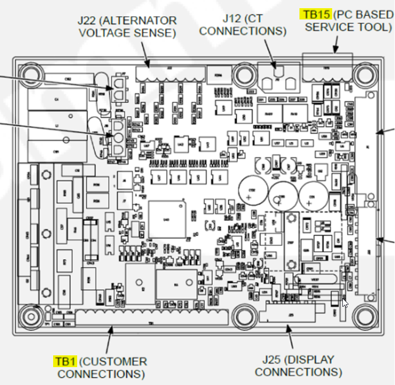
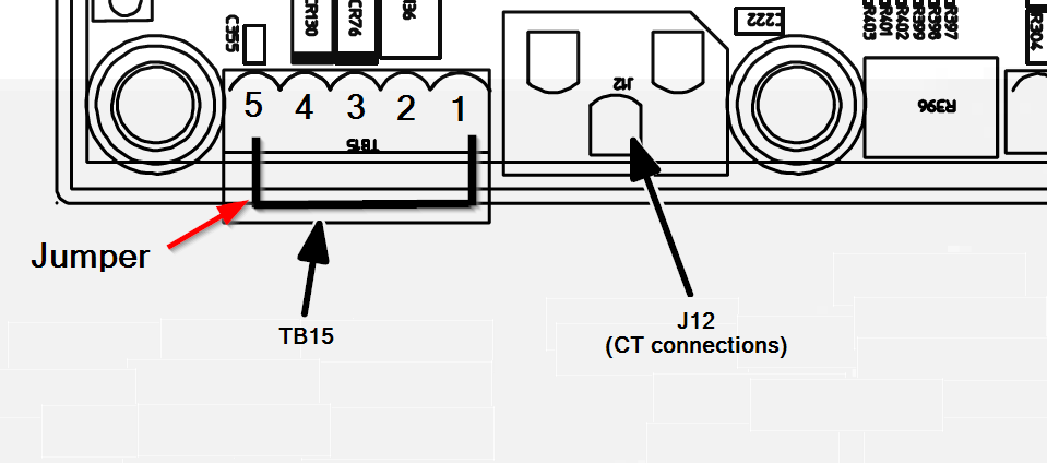
Jumper wire will need to be connected between TB15-1 and TB15-5 to disable sleep mode and keep RS485 port active at all times.
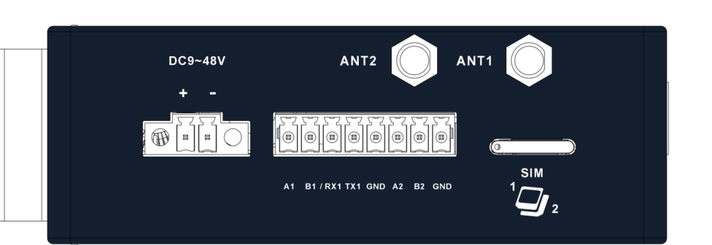
Generac Gateway Side Terminations
|
Description
|
Harness Wire Color
|
Equipment Side Terminations
|
|---|---|---|---|
|
+ |
DC+ |
Red |
TB1-5 |
|
- |
DC- |
Black |
Ground Terminal |
|
A2 |
Data + |
Blue / White |
TB15-3 |
|
B2 |
Data - |
White / Blue |
TB15-4 |
|
GND |
Data GND |
White / Green |
TB15-1 |
|
Harness Relay #1 |
COM |
Blue |
TB1-10 |
|
N/O |
White / Blue |
TB1-11 |
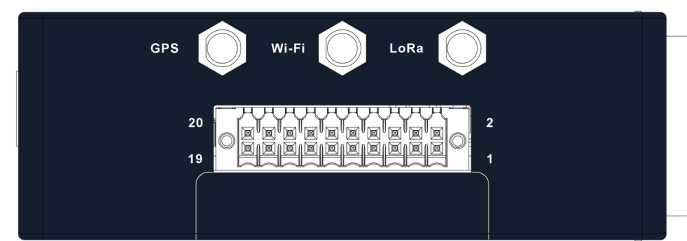
Gateway Connection Ports
Check out our knowledge base and support center for information on any technical questions.