
This topic is the install guide for the after-market gateway (part# A0009887841) with the GL899-PARTIAL POWER HARNESS (part# A0009887769) when utilizing the Generac Power Zone Pro® and Power Zone Pro Sync via an Ethernet connection.
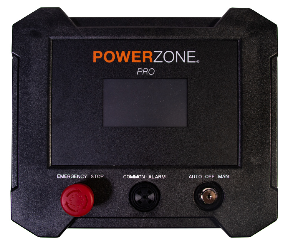
Generac Power Zone Pro
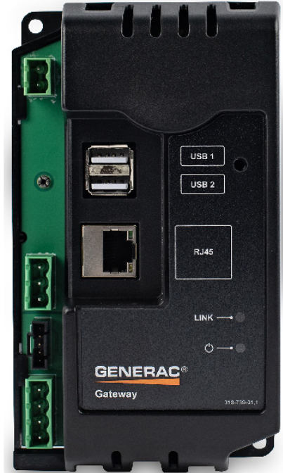
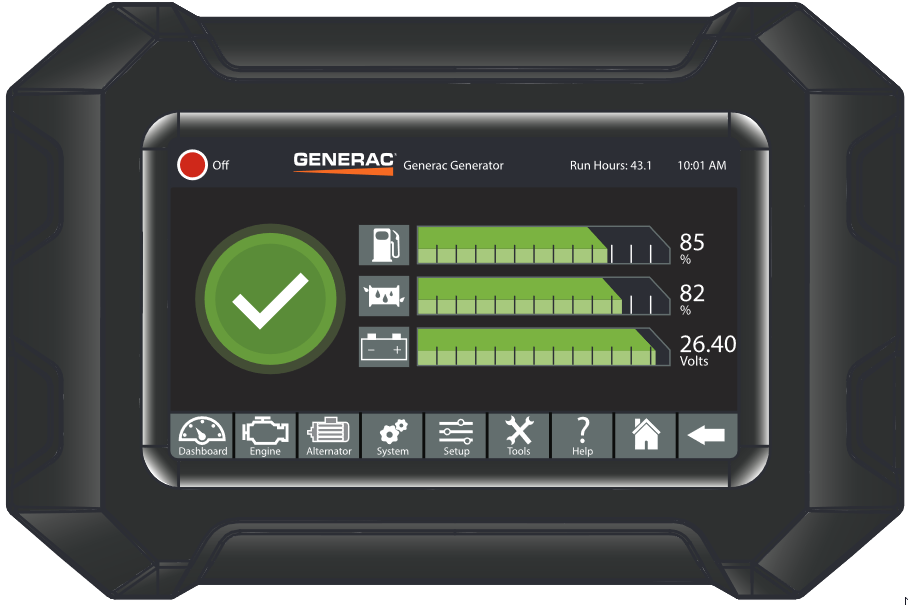
Generac Power Zone Pro Sync
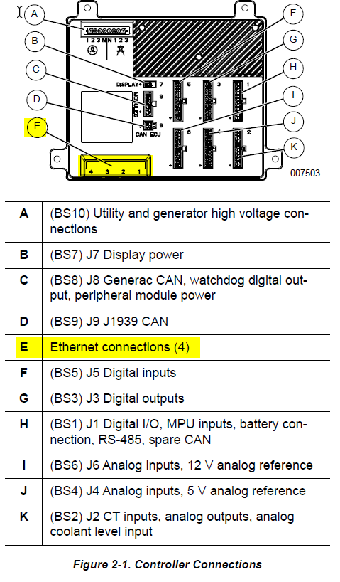
Generac Link-Site Deployment Controller Selection:
Generac Power Zone Pro-TCP
Modbus Communication Settings and Notes
To confirm port settings, follow the guidelines listed in this section. Settings should correspond to the values provided in the table.
|
IP: 192.168.3.2 |
|
Subnet: 255.255.255.0 |
|
DNS: Leave Blank |
|
Gateway: 192.168.3.100 |
For firmware version 1.21.9 and prior:
-
Navigate to Setup>Communications>Modbus Pass Thru.
-
Modbus TCP Enable and Ignore Unit ID toggles should both be checked.
-
Confirm that the IP settings correspond to the values in the table.
For firmware version 1.22.1 or newer:
-
Navigate to Setup>Communications>External Interfaces> Ethernet Built In>Configure>Modbus Gateway >Configure.
-
Modbus TCP Enable and Ignore Unit ID toggles should both be checked.
-
Confirm that the IP settings correspond to the values in the table.
If different settings are required, please contact Support.
Equipment Connection Details
Generac Gateway Side Terminations
|
Description
|
Harness Wire Color
|
Equipment Side Terminations
|
|---|---|---|---|
|
2 |
DC+ |
A0009887769 Red |
B+ |
|
1 |
DC- |
A0009887769 Black |
B- |
|
ETH1 |
Modbus TCP |
*CAT5 cable |
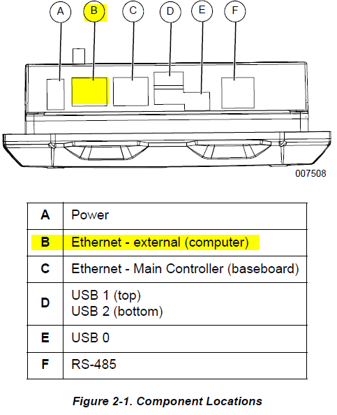
‘COMPUTER’ /
|
*included in harness accessory kit.
Gateway Connection Ports
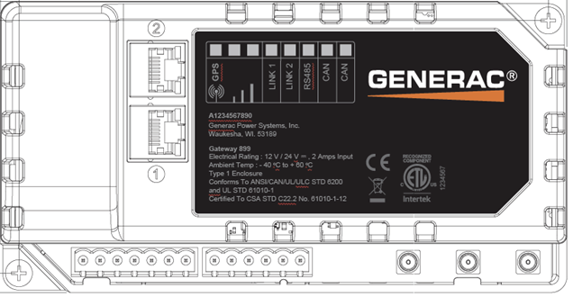
|
Pin |
Connector |
Description |
|
1 |
A |
Plant Supply –ve |
|
2 |
Plant Supply +ve |
|
|
3 |
Digital Output A |
|
|
4 |
Digital Output B |
|
|
5 |
Flexible Sender Common |
|
|
6 |
Flexible Sender A |
|
|
7 |
Flexible Sender B |
|
|
1 |
B
|
RS485 A |
|
2 |
RS485 B |
|
|
3 |
RS485 Screen |
|
|
4 |
CAN H |
|
|
5 |
CAN L |
|
|
6 |
CAN Screen |
Check out our knowledge base and support center for information on any technical questions.