
After-Market Kit Installation and Troubleshooting Guide (Version 3)
The latest Aftermarket Gateway kit (A0009887841) has several harness options for ordering. The latest aftermarket options is designed to support have more granularity if the exact installation needs are known but also an option for a universal kit that would work with all equipment make/models.
These harnesses and accessories enable remote control and monitoring of backup power equipment leveraging Generac Link Manager, our cloud solution for industrial IoT connectivity. This topic offers wiring and hardware details as well as some troubleshooting steps for a complete setup that enables continuous communications and remote access.
Commissioning the Gateway
This topic details the hardware components and installation steps needed to commission an IoT-enabled generator and associated equipment.
Be sure to check out our FAQs for answers to common questions.
Tools Needed
Technicians should bring the following hardware and software to the installation.
On Hand | Hardware and Documentation |
Access to Genlink software (specific to Generac controllers) | |
Modbus master simulator such as Modscan64 | |
Windows Laptop | |
USB to serial connector | |
Mini flat head screw driver |
Other checklist items for Site Deployment include verifying voltage and the condition of circuit fuses. Please follow the steps in this table.
Pass/Fail | Site Deployment Prerequisites |
| |
| |
| |
|
Installation Steps
The remaining steps needed for a complete installation are provided in this section, which details kit components.
Identify components included in the kit as provided in the previous section.
In the event that any of these parts arrive damaged, please contact Support to open a ticket and request needed replacements.
Identify existing din rail. Gateway should be mounted in interior of gen controller enclosure where possible to limit vibration and weather exposure.
Magnets and mounting hardware are available in the COMMS AND INSTALLATION ACCESSORY KIT
Connect included cell antennae to Main and Diversity ports on side of the gateway. Mount as close to outside of generator enclosure as possible. Antennae ends should be separated approximately 12”-18”. Installation of a drip loop is required to keep water from entering unit.
Connect included GPS antenna to GPS port on side of gateway. Mount as close to outside of generator enclosure as possible. Installation of a drip loop is required to keep water from entering unit.
Inspect wiring harness and make sure it meets the needs of the use case. Given below are few use cases for guidance. Once verified, identify customer and gateway ends on the harness. Note that there are four (4) distinct harness types available for connection.
GL899 Connection Method | Harness needed | Equivalent Kit |
|---|---|---|
TCP connection with all monitoring and control capability available via Modbus | A0009887769 | N/A - no kit required |
RS485 connection with all monitoring and control capability available via Modbus | A0009887769, A0009887770 | A0009887842 - |
TCP connection but needs either 1 or 2 inputs and/ or to drive 1 or 2 digital outputs | A0009887772 | N/A - no kit required |
RS485 connection but needs either 1 or 2 inputs and/ or to drive 1 or 2 digital outputs | A0009887772, A0009887770 | A0009887843 - UNIVERSAL INSTALLATION |
RS232 connection with all monitoring and control capability available via Modbus | A0009887769, A0009887770, A0009887771 | A0009887842 - |
RS232 connection but needs either 1 or 2 inputs and/ or to drive 1 or 2 digital outputs | A0009887772, A0009887770, A0009887771 | A0009887843 - UNIVERSAL INSTALLATION |
Monitoring via CAN J1939 but needs either 1 or 2 inputs and/ or to drive 1 or 2 digital outputs | A0009887772, A0009887770 | A0009887843 - UNIVERSAL INSTALLATION |
Route customer end to be near generator termination points. See generator controller specific reference pages for recommended terminations.
Make final connections on customer end per documentation.
If included ethernet cable is being used for modbus communication to equipment, connect to the port labeled 1 on gateway.
External device will need to be programmed with like IP address for communication to be established.
Default ETH1 Port Settings: | Recommended Equipment |
|---|---|
IP Address: 192.168.3.100 | IP Address: 192.168.3.2 |
If default or recommended settings can not be used contact Generac customer support (Option 4 ) or email at support@energyservices.generac.com
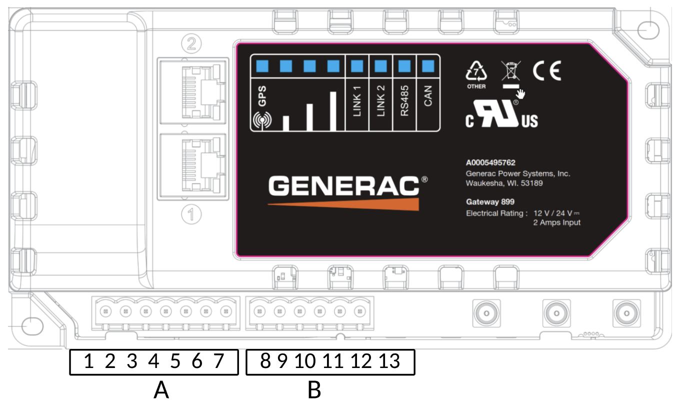
Wire Termination Setup Detail
The table below outlines each connection for the advanced aftermarket gateway and universal harness, detailing how they interface with the equipment to be monitored.
We recommend scheduling time with a Generac solutions engineer before attempting to connect multiple assets through one gateway. For example, if your site hosts multiple generators, ATSs, or fuel sensors, more advanced support may be required to communicate via one gateway.
Generac Gateway Side Termination | Description | Harness Wire Color | Customer Side Terminations |
1 | DC- | Red | Battery(+) |
2 | DC+ | Black | Battery(-) |
Harness Relay#1 | COM | Blue | 2-Wire Gen Start |
NC | Blue/ White | ||
NO | White/ Blue | ||
Harness Relay#2 | COM | Brown | Spare Output |
NC | White/ Orange | ||
NO | Green/ Yellow | ||
5 | Common | Black | N/A |
6 | Digital Input1 + [See Note Below] | Purple | Engine Running |
7 | Digital Input2 + [See Note Below] | Green | Not In Auto |
8 | RS485 A | Orange/White | RS485+ |
9 | RS485 B | White/Orange | RS485- |
10 | RS485 Screen | Blue/White | RS485 GND |
11 | CAN H | Orange/White | CAN H |
12 | CAN L | White/Orange | CAN L |
13 | CAN Screen | Blue/White | CAN Screen |
GL899 ‘digital’ inputs support reading of analog voltages. In order to use them as digital inputs connect the field side contact COM terminal to DC negative (black wire). Connect the other terminal of the contact to either Purple or Green wires. Make sure that voltage between Common and Normally open side of the field contact never drops below 9VDC.
If the field side contact is sourcing, DC+ is present when contact is closed, additional isolation relays are required. Instead, drive a separate 12V/ 24VDC (depending on battery voltage) relay. The relay contacts (NO and COM) can then be connected such that COM connects to battery negative ( - ) and NO connects to either purple or green wire on terminals 6/7 on the gateway device.
Troubleshooting
Check this section to resolve any issues experienced while setting up the Advanced Gateway.
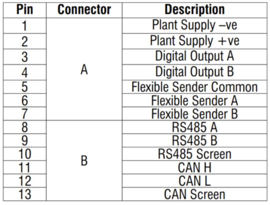
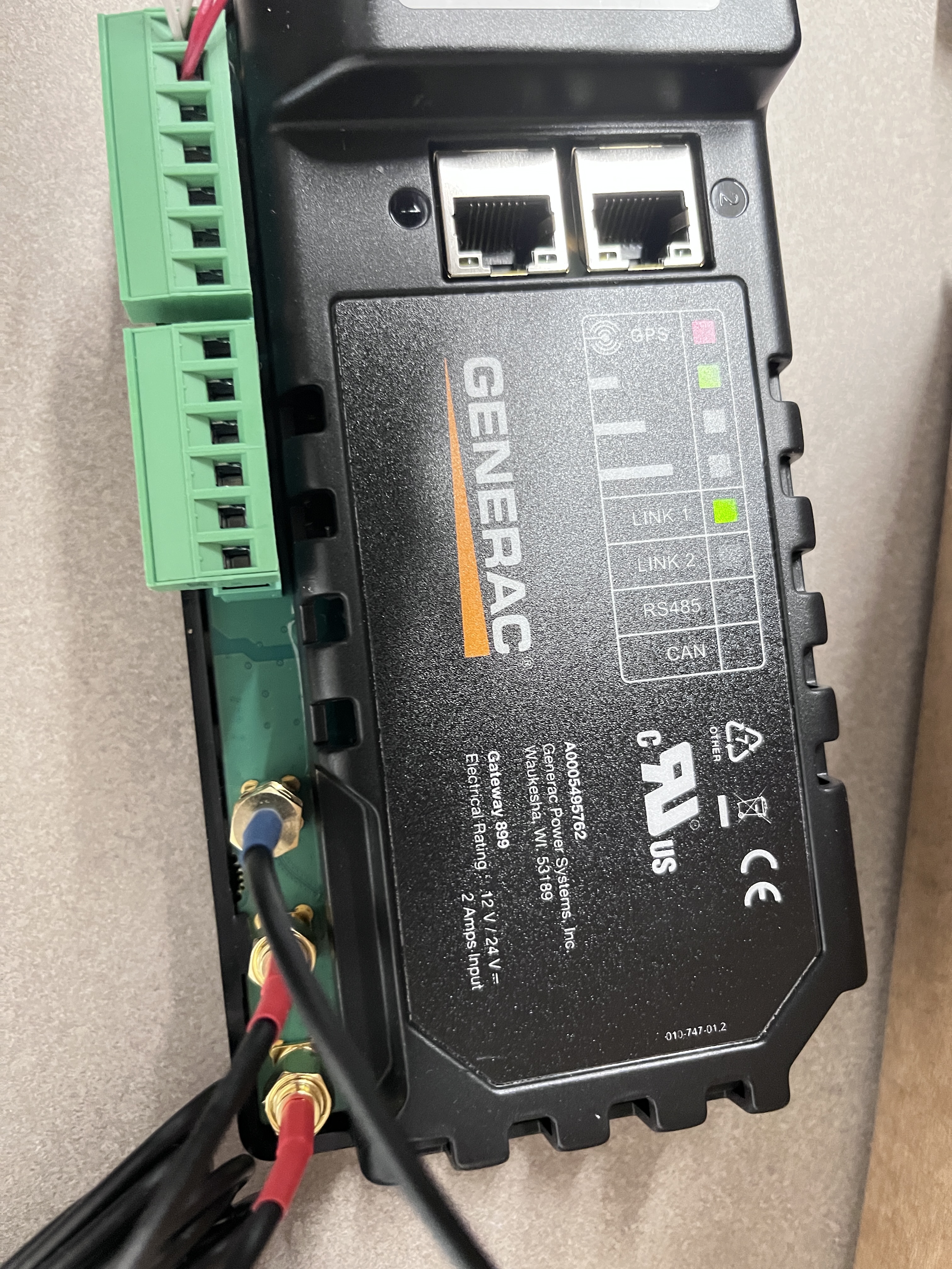
Front Panel Indicators and Components
Front Panel Component | Description |
GPS LED | Solid RED when gateway is powered on with no location lock. Solid GRN when location lock is made. |
Cellular signal bar LEDs | Solid GRN showing number of bars for signal strength. Solid RED when cell connectivity is not established. |
LINK1 LED | Solid when gateway is successfully connected to Generac Link cloud services. |
LINK2 LED | |
RS485 LED | Blinking green when gateway device is trying to connect to Modbus server (slave) device. May blink so fast that it looks solid GRN. Off when gateway device has not been configured to use RS485 communication |
CAN LED | Blinking green when gateway device is configured to use CAN Bus and transmitting/ receiving on CAN network |
1 | Ethernet Connection via static IP |
2 | Ethernet Connection via DHCP |
GPS antenna Terminal | GPS antenna connection |
Main antenna Terminal | GSM cellular antenna connection |
Diversity antenna Terminal | GSM cellular antenna connection |
Verifying Proper SIM Installation
Power off the gateway.
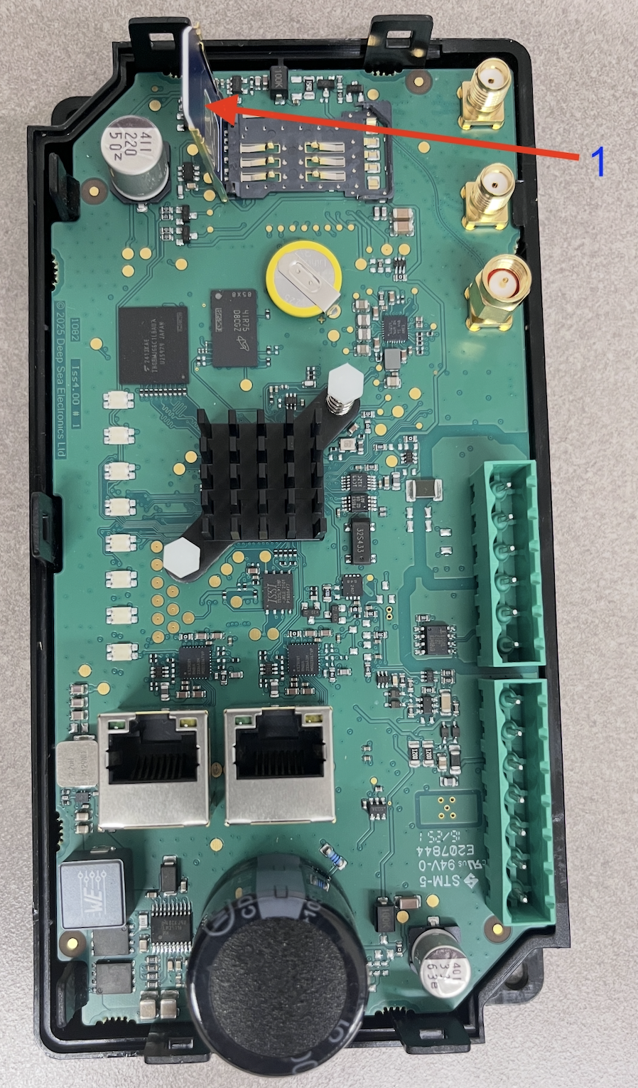
To open the SIM card slot, check the image below and follow the procedure given here
#1 - Insert a flat head screw driver and push the notch back
#2 - At this time pull the top cover
#3 - Next push the notch with flat head screw driver
#4 - Pull up the cover
#5 - Pull up the other end of cover
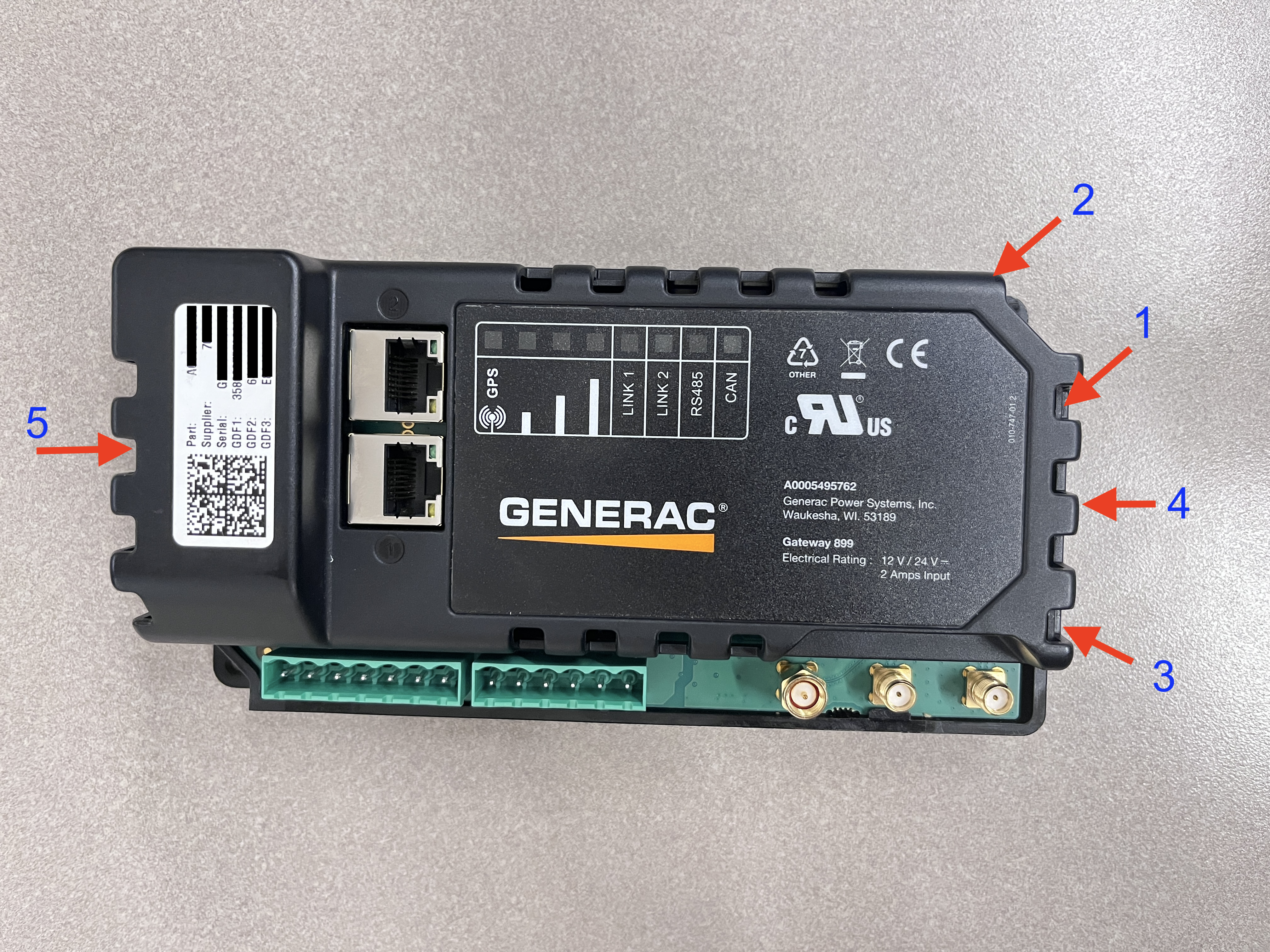
Verify that the SIM card on arrival is inserted in the slot, as depicted in the photo, with chip wiring facing down.
To replace the SIM or insert a new one, push the SIM cover back with thumb away from antenna terminals. Then insert the SIM in the slot, close the cover and push the cover back towards antenna terminals.
Using a LAN-Based Internet Connection
For LAN wired internet connectivity, ports 443, 5671, and 8883 must be opened for outbound traffic on the facility firewall, if applicable. The customer-provided Ethernet connection must be configured to assign the Generac Link gateway an IP address via DHCP and connected to port 2.
Run network cable from customer’s nearest network infrastructure to a laptop.
Verify that the network cable has an active internet connection by opening a web browser and attempting to access http://www.google.com .
If laptop test is successful, connect Ethernet cable to port 2 on the gateway. If test is not successful work with facility IT to resolve.
Power off the gateway.
Remove SIM card(s) from the gateway.
Power on the gateway.
Wait 10–15 minutes then check the Generac Link Manager for live data streaming. If it is not communicating, please reach out to Support.
A computer based call using Microsoft Teams may be needed to share your screen with on of our solutions engineers.
Changing Communication Option from Serial to Ethernet
Enable the Modbus TCP port on the asset controller.
Set the controller IP address in 192.168.3.x (any value, with the exception of 192.168.3.100).
Set subnet mask to 255.255.255.0.
Run ethernet cable and connect to asset controller Modbus TCP port as well as port 1 on Generac Link gateway.
Contact Support to reconfigure site for Modbus TCP communications.
If controller IP address cannot be changed due to site restrictions, please reach out to a Solutions Engineer.
If the technician does not have password to change communication setup on controller, reach out to the IDC master tech or to the generator support team.
If the technician does not know where to change the communication setup, reach out to the IDC master tech or generator support team.
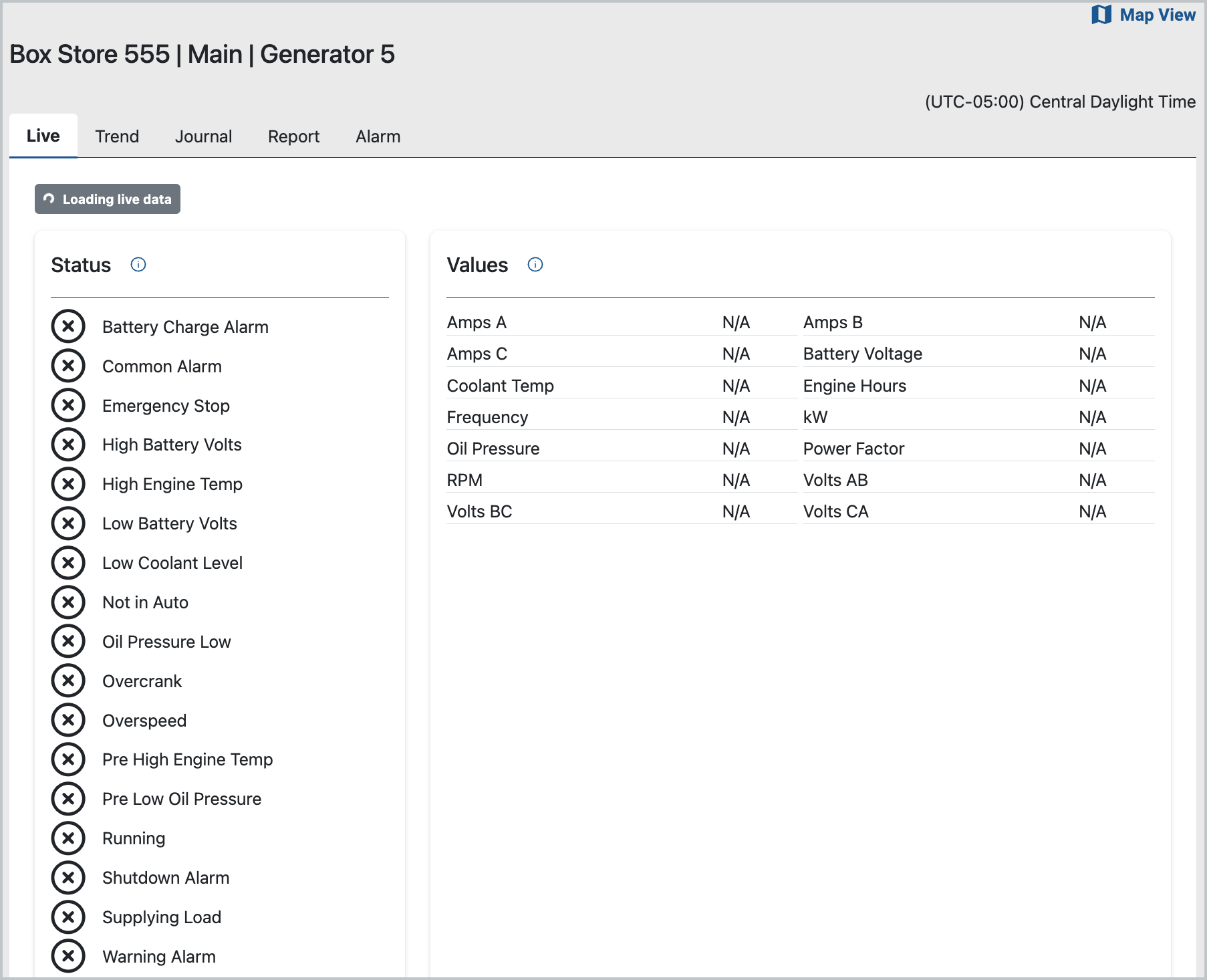
Data Values of N/A
A connectivity issue may exist between the gateway and the network.
Possible Connectivity Issue
Steps to resolve
Confirm that the device is on by checking at least one of GPS or cell signal strength lights are on.
If all lights are Off, check voltage at 1 and 2 terminals.
To verify the gateway's connectivity, check the cell signal strength lights. At least one solid green light indicates an active cellular connection, a solid red light indicates no connection is made. If cell strength light is red check the following:
Ensure both red antennas connections are securely connected to the main and diversity ports on the gateway and positioned to maximize cellular signal strength. After confirmed, reboot gateway.
Verify Verizon coverage using Verizon’s coverage checker.(https://www.verizon.com/coverage-map/). If needed, check whether alternative carriers (such as AT&T or T-Mobile) provide better reception. We recommend consulting local site contacts for assistance.
Cycle power to gateway.
If the above are verified OK and the application still indicates N/A in the data stream, please contact Support.
Values of -99 Populate Data Stream
A value of -99 indicates a Modbus communication issue.
To resolve this issue, take the following steps:
Verify that the asset communication port settings align with the specifications in the controller-specific installation instructions.
Confirm proper wiring connections between the gateway and controller.
Power cycle the equipment controller.
One or Both Relays on Wire Harness Not Functioning
Command to trigger on/off from platform is failing
Make sure there are no –99 values shown on the platform for the equipment under consideration.
Listen for click sound when a particular output is triggered on/off from platform.
Sound may become overwhelmed/masked by the noise of other equipment.
Connect a multi-meter in continuity measurement mode between Blue and White/Blue wires for checking relay #1 or Brown and Green/ Yellow wires for checking relay #2.
Be sure to disconnect wires from the controller, which must be absent any voltage before testing. When the output is initiated from the platform, relay contacts should close and when turned off, the contacts should open.
If the above steps do not resolve the issue, the harness may need to be replaced. To do so, place an order using part number A0009887772 by submitting a Support ticket. Once the new harness arrives, follow these steps again.