
Generac Power Zone Pro (Sync) via Ethernet (V3)
This topic is the install guide for the after-market gateway (part# A0009887841) with the GL899-PARTIAL POWER HARNESS (part# A0009887769) when utilizing the Generac Power Zone Pro® and Power Zone Pro Sync via an Ethernet connection.
Generac Power Zone Pro
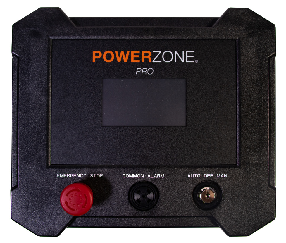
Power Zone Pro Display Panel
Connect to Power Zone Gateway for programming and Modbus TCP connection.
Generac Power Zone Pro Sync
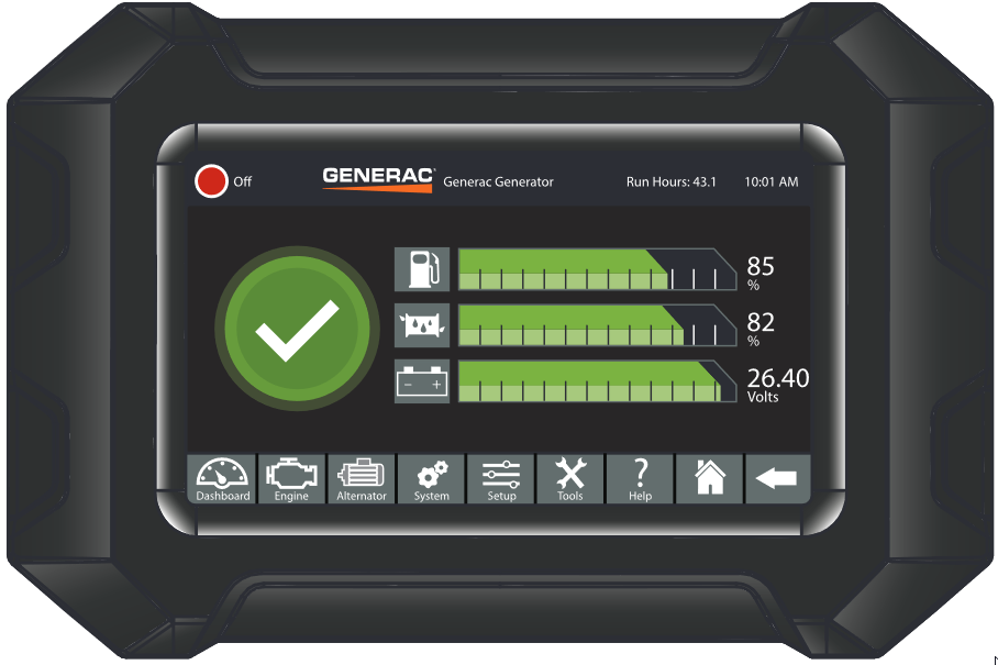
Display COMPUTER port can be used for programming and Modbus TCP connection.
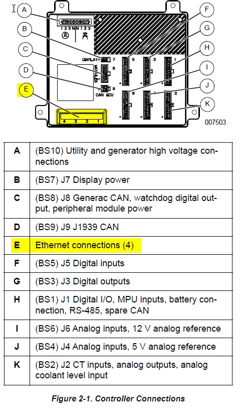
Base controller Ethernet ports can be used for programming.
Generac Link-Site Deployment Controller Selection:
Generac Power Zone Pro-TCP
Modbus Communication Settings and Notes
To confirm port settings, follow the guidelines listed in this section. Settings should correspond to the values provided in the table.
IP: 192.168.3.2 |
Subnet: 255.255.255.0 |
DNS: Leave Blank |
Gateway: 192.168.3.100 |
For firmware version 1.21.9 and prior:
Navigate to Setup>Communications>Modbus Pass Thru.
Modbus TCP Enable and Ignore Unit ID toggles should both be checked.
Confirm that the IP settings correspond to the values in the table.
For firmware version 1.22.1 or newer:
Navigate to Setup>Communications>External Interfaces> Ethernet Built In>Configure>Modbus Gateway >Configure.
Modbus TCP Enable and Ignore Unit ID toggles should both be checked.
Confirm that the IP settings correspond to the values in the table.
If different settings are required, please contact Support.
Equipment Connection Details
Generac Gateway Side Terminations | Description | Harness Wire Color | Equipment Side Terminations |
|---|---|---|---|
2 | DC+ | A0009887769 Red | B+ |
1 | DC- | A0009887769 Black | B- |
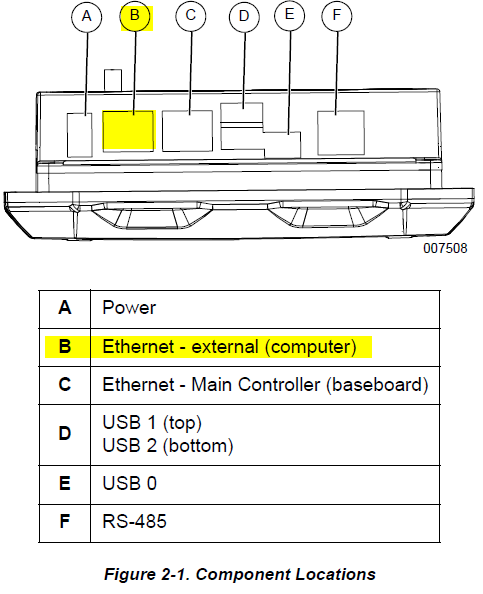
ETH1 | Modbus TCP | *CAT5 cable | ‘COMPUTER’ / |
*included in harness accessory kit.
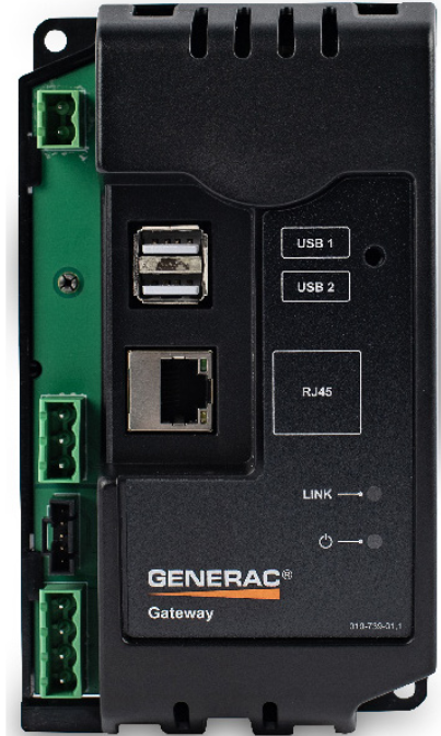
Gateway Connection Ports
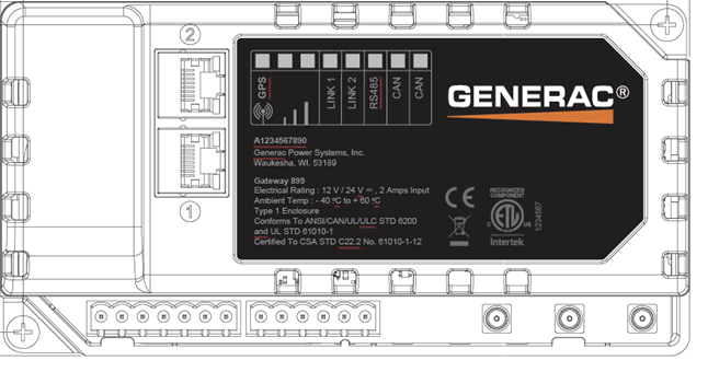
Pin | Connector | Description |
1 | A | Plant Supply –ve |
2 | Plant Supply +ve | |
3 | Digital Output A | |
4 | Digital Output B | |
5 | Flexible Sender Common | |
6 | Flexible Sender A | |
7 | Flexible Sender B | |
1 | B
| RS485 A |
2 | RS485 B | |
3 | RS485 Screen | |
4 | CAN H | |
5 | CAN L | |
6 | CAN Screen |
Check out our knowledge base and support center for information on any technical questions.