
Generac Power Zone 410 Controller (V3)
This topic is the install guide for the after-market gateway (part# A0009887841) with the GL899-PARTIAL POWER HARNESS (part# A0009887769), GL899-PARTIAL COMM HARNESS (part# A0009887770) utilizing the Generac PowerZone® 410 Controller.
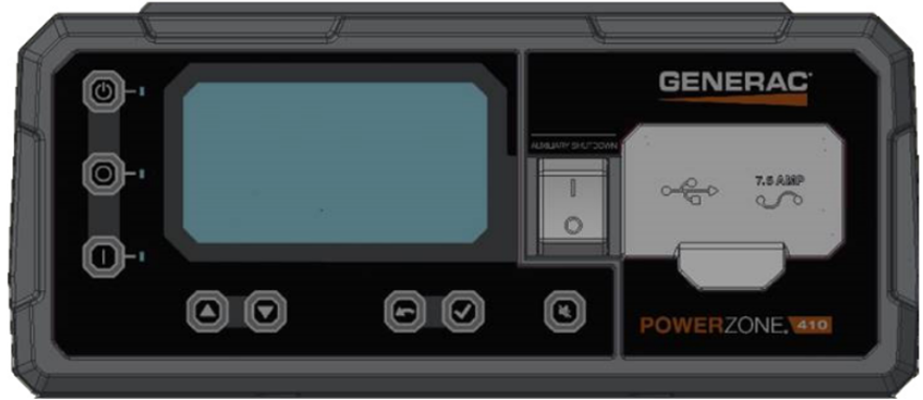
Generac Power Zone 410 Controller Display
Power Zone 410 Wiring and Connections
Generac Link-Site Deployment Controller Selection:
Genera Power Zone 410-RS485
Modbus Communication Settings and Notes
Settings should correspond to the values provided in this table.
Address: 157 | Data Bit: 8 |
Baud Rate: 9600 | Stop Bit: 1 |
Parity: None | |
If different settings are required, please contact Support.
From the control panel as depicted in the schematic in this section, follow the steps provided here.
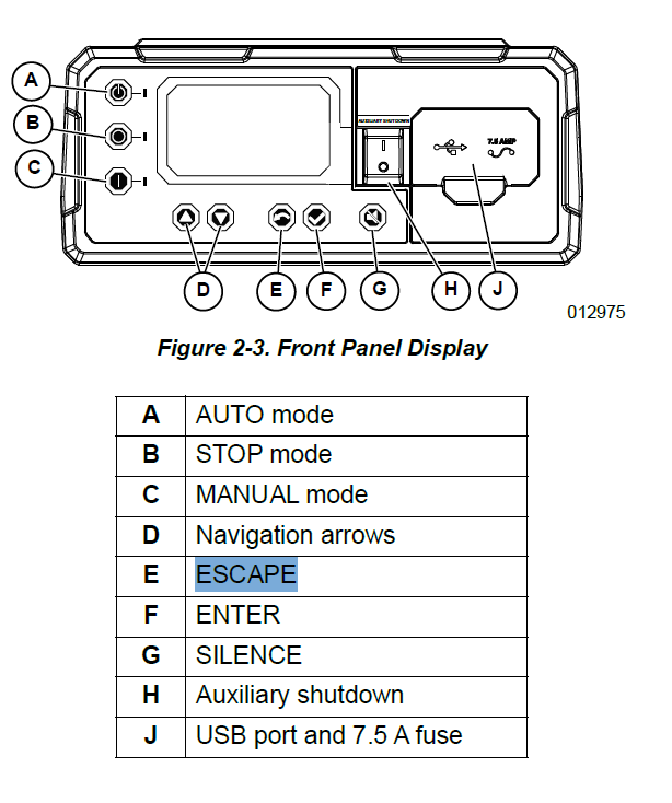
Front Panel Display
RS485 slave port configuration can be reached through Dealer Menu by entering the Dealer Code.
Edit Settings>Config RS485 Slave.
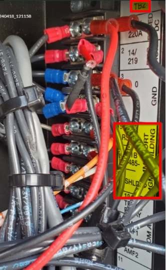
Equipment Connection Details
Generac Gateway Side Terminations | Description | Harness Wire Color | Equipment Side Terminations |
|---|---|---|---|
2 | DC+ | A0009887769 Red | B+ |
1 | DC- | A0009887769 Black | B- |
8 | Data + | A0009887770 Orange / White | TB2—RS485+ |
9 | Data - | A0009887770 White / Orange | TB2—RS485- |
10 | Data GND | A0009887770 Blue/ White | TB2—SHLD |
Gateway Connection Ports
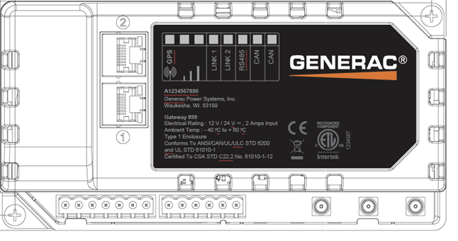
Pin | Connector | Description |
1 | A | Plant Supply –ve |
2 | Plant Supply +ve | |
3 | Digital Output A | |
4 | Digital Output B | |
5 | Flexible Sender Common | |
6 | Flexible Sender A | |
7 | Flexible Sender B | |
1 | B
| RS485 A |
2 | RS485 B | |
3 | RS485 Screen | |
4 | CAN H | |
5 | CAN L | |
6 | CAN Screen |
Check out our knowledge base and support center for information on any technical questions.