
Generac G Panel (Stand Alone) (V3)
This topic is the install guide for after-market Gateway (part# A0009887841) with the GL899-PARTIAL POWER HARNESS (part# A0009887769), GL899-PARTIAL COMM HARNESS (part# A0009887770) and the GL899-COMM ACCESSORIES( part# A0009887771) utilizing the Generac G Panel (stand alone single generator application).
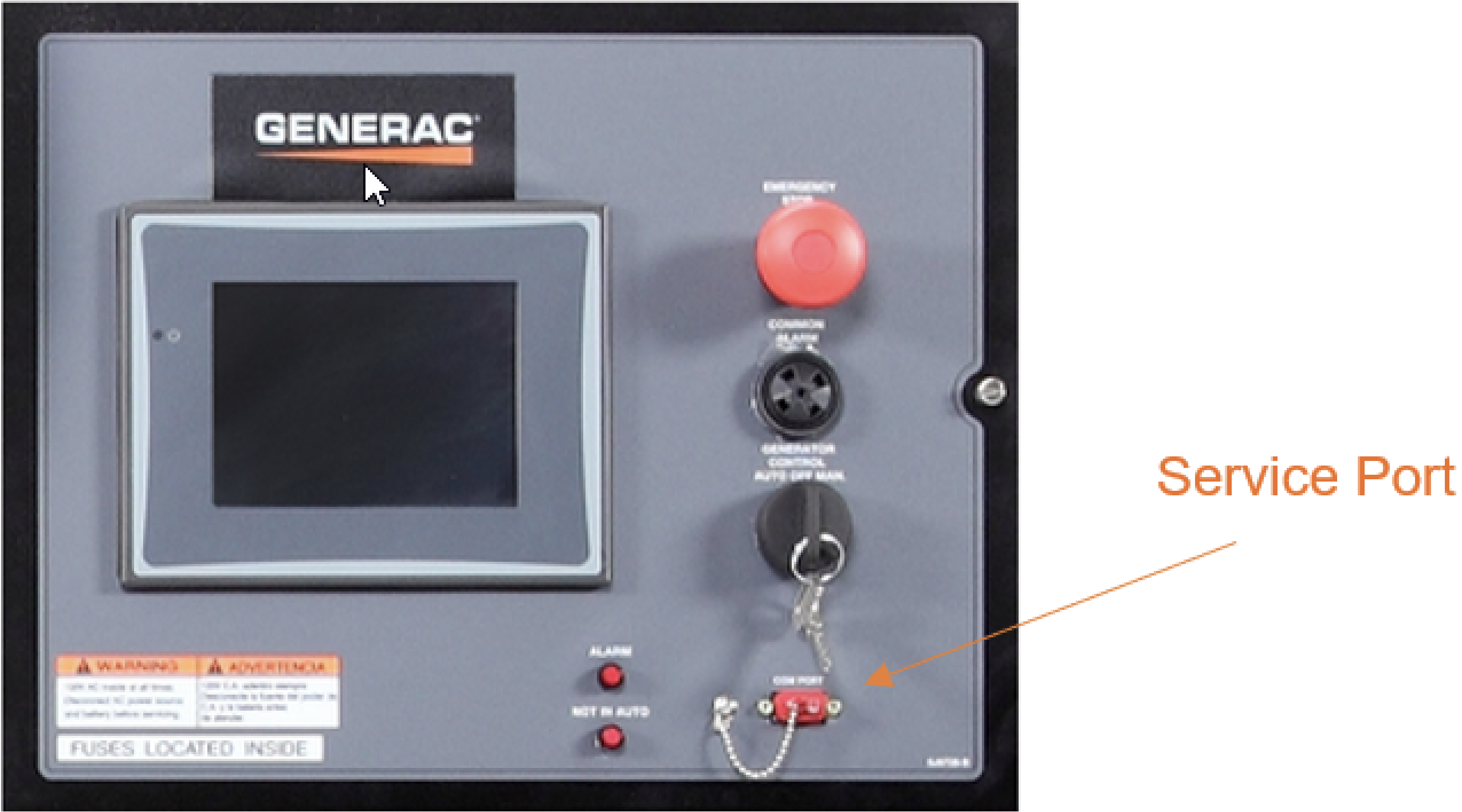
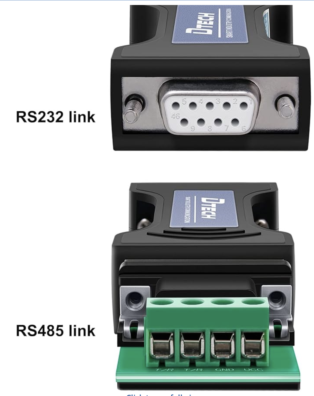
The GL899 does not have an RS232 port, and requires a RS232 to RS485 converter (DTech DT9000 included in A0009887771 accessories kit). Connect the converter to G Panel service port.
Generac Link-Site Deployment Controller Selection:
Generac G Panel-RS485
Modbus Communication Settings and Notes
Settings should correspond to the values in the table provided.
Address: 100 |
Baud Rate: 9600 |
Mode: Modbus Slave |
If different settings are required, please contact Support.
Equipment Connection Details
Generac Gateway Side Terminations | Description | Harness Wire Color | Equipment Side Terminations | DTECH |
|---|---|---|---|---|
2 | DC+ | A0009887769 Red | TB1-1 | |
1 | DC- | A0009887769 Black | TB1-2 | |
8 | Data + | A0009887770 Orange / White | T/R+ | |
9 | Data - | A0009887770 White / Orange | T/R- | |
10 | Data GND | A0009887770 Blue/ White | GND |
Gateway Connection Ports

Pin | Connector | Description |
1 | A | Plant Supply –ve |
2 | Plant Supply +ve | |
3 | Digital Output A | |
4 | Digital Output B | |
5 | Flexible Sender Common | |
6 | Flexible Sender A | |
7 | Flexible Sender B | |
1 | B
| RS485 A |
2 | RS485 B | |
3 | RS485 Screen | |
4 | CAN H | |
5 | CAN L | |
6 | CAN Screen |
Check out our knowledge base and support center for information on any technical questions.