
Generac Evolution Hardwired I/O (V3)
This topic is the install guide for the after-market gateway (part# A0009887841) with A0009887772 (GL899-PARTIAL RETROFIT HARNESS) utilizing the Generac Evolution control panel.

Panel Display for Evolution (Air Cooled) Control Panel
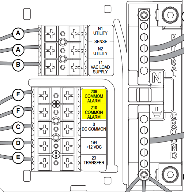
Evolution Control Wiring (60Hz) 2016 and Older (Behind Control Board)
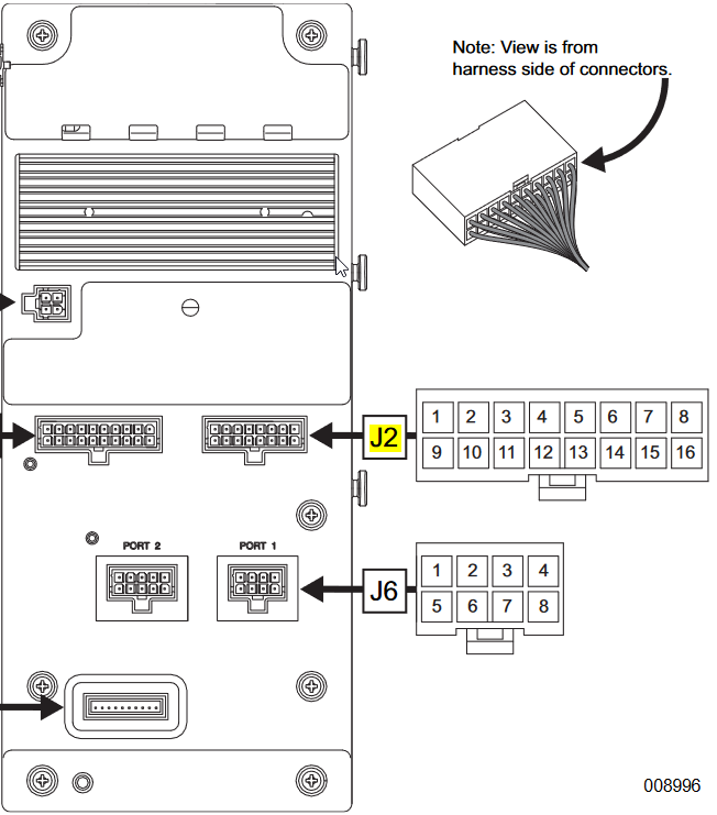
Evolution 1.0 and 2.0 Controller Connections
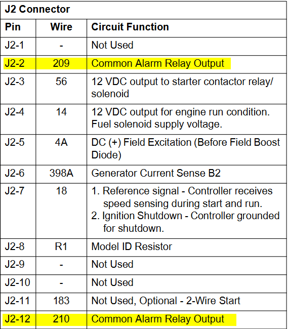
Evolution 1.0 - J2 Connector detail
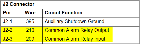
Evolution 2.0—J2 Connector Detail
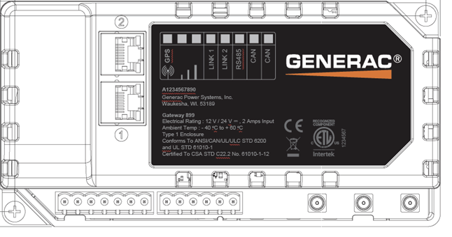
Generac Link-Site Deployment Controller Selection:
Hardwired-DSE899
Equipment Connection Details
Generac Gateway Side Terminations | Description | Harness Wire Color | Equipment Side Terminations |
|---|---|---|---|
2 | DC+ | Red | B+ |
1 | DC- | Black | B- |
6 | Engine Running | Purple | Fuel Solenoid+ (Red) |
7 | Common Alarm | Green | Terminal/Wire 210 |
Harness Relay #1 | COM | Blue | Remote Start—178 |
N/O | White / Blue | Remote Start—183 |
Note that when using A0009887772 harness, terminal 5 on Generac Gateway is connected to battery negative. Therefore the common terminal on equipment controller Engine Running and Not in Auto signals should be connected to battery positive and the signals should be connected to the terminals mentioned in above table. In other words, this means outputs on equipment controller must source voltage to Generac Gateway inputs.
If the equipment controller outputs are sinking voltage, a 12/ 24 vdc (depending on battery voltage) relay needs to be connected between the controller output (for example, engine running) and common. The relay N/O contact would connect to terminal 6 on Generac Gateway and relay COM connects to battery positive post
Gateway Connection Ports
Pin | Connector | Description |
1 | A | Plant Supply –ve |
2 | Plant Supply +ve | |
3 | Digital Output A | |
4 | Digital Output B | |
5 | Flexible Sender Common | |
6 | Flexible Sender A | |
7 | Flexible Sender B | |
1 | B
| RS485 A |
2 | RS485 B | |
3 | RS485 Screen | |
4 | CAN H | |
5 | CAN L | |
6 | CAN Screen |
Check out our knowledge base and support center for information on any technical questions.