
Generac Evolution Controller (V3)
This topic is the install guide for the after-market gateway (part# A0009887841) with harness (part# A0009887770, A0009887771, A0009887772) utilizing the Generac Evolution (Air or Liquid Cooled) control panel via Modbus.
NOTE: Please reach out to Generac generator support team or Generac Link support team at least a week in advance with generator serial number. Generac must confirm if the Evolution controller on the generator is capable of supporting advacned data. Please do not proceed onsite without confirmation.

Panel Display for the Generac Evolution Control
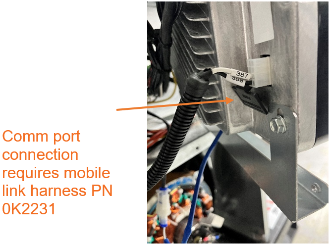
Close View of Port Connections
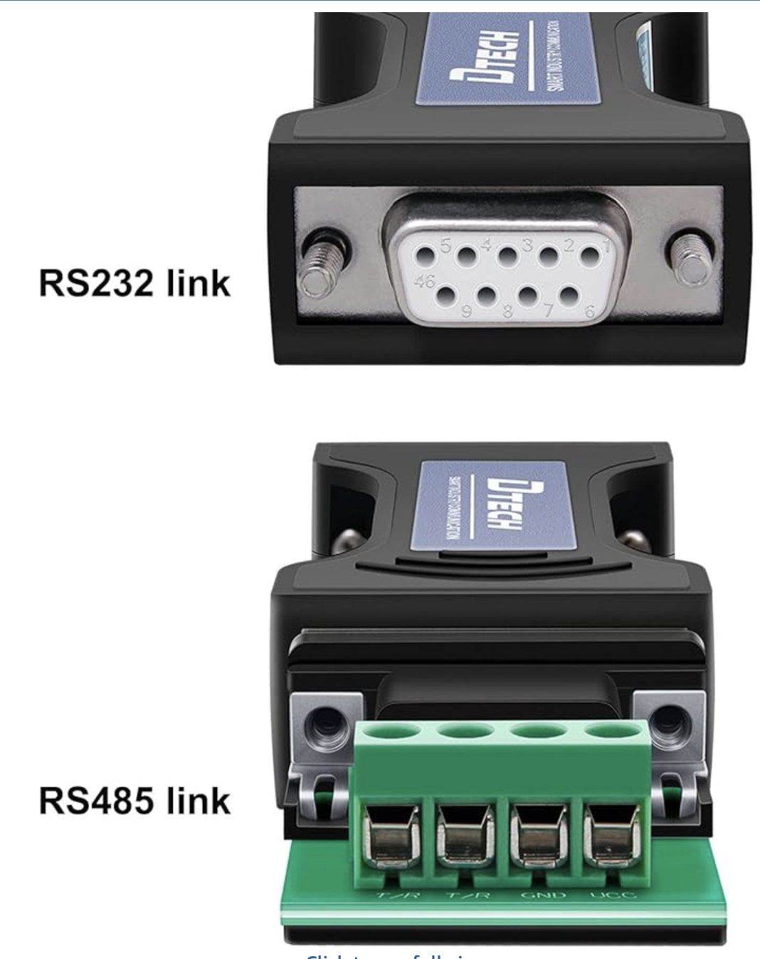
The GL899 does not have an RS232 port, and requires a RS232 to RS485 converter (DTech DT9000 included in A0009887771 accessories kit). An additional breakout board is required to jump Mobile Link wire harness comm wires to RS232 link side of converter.
Generac Link-Site Deployment Controller Selection:
Generac Evolution-RS485
Communication Settings and Notes
Settings should correspond to the values provided in this table.
Address: 157 | Data Bit: 8 |
Baud Rate: 115200 | Stop Bit: 1 |
Parity: None | |
Please refer to Generator installation/ control manuals available on Genservice for information about how to view/ edit communication settings. If Modbus configuration on the controller are different than what is mentioned above, please change the configurations on the Evolution controller to match above.
Note that Evolution controller does not support faster polling. The polling rate will be every 1 second
Equipment Connection Details
Generac Gateway Side Terminations | Description | Harness Wire Color | Equipment Side Terminations | S232 DB9 breakout* | DTECH |
|---|---|---|---|---|---|
2 | DC+ | A0009887772 Red | Battery + | ||
1 | DC- | A0009887772 Black | Battery - | ||
8 | Data + | A0009887770 Orange / White | 388 (Connector J6—Pin#7) | 3-TXD | T/R+ |
9 | Data - | A0009887770 White / Orange | 387 (Connector J6—Pin#8) | 2-RXD | T/R- |
10 | Data GND | A0009887770 Blue/ White | Connect to Pin 4 of J6 connector. Note that there is no labelled wire for this pin. The harness wire needs to be inserted and secured on the pin using a tweezer tool by installer | 5-GND | GND |
Harness Relay #1 | COM | A0009887772 Blue | Remote Start—178 | ||
N/O | A0009887772 White / Blue | Remote Start—183 |
Additional breakout board is required to breakout board cover to protect connections and secure to service port.
The DSE899 does not have an RS232 port, hence we need to use a DTECH DT-9000 RS232 to RS485 converter.
* DB9 breakout board needs to be procured separately by installer.
Gateway Connection Ports
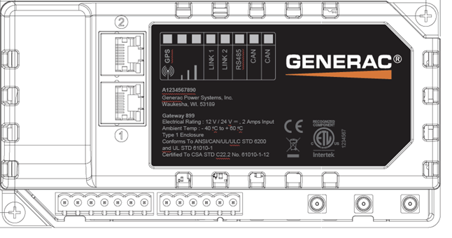
Pin | Connector | Description |
1 | A | Plant Supply –ve |
2 | Plant Supply +ve | |
3 | Digital Output A | |
4 | Digital Output B | |
5 | Flexible Sender Common | |
6 | Flexible Sender A | |
7 | Flexible Sender B | |
1 | B
| RS485 A |
2 | RS485 B | |
3 | RS485 Screen | |
4 | CAN H | |
5 | CAN L | |
6 | CAN Screen |
Check out our knowledge base and support center for information on any technical questions.