Installing and Troubleshooting the Gateway
The Advanced Gateway enables remote monitoring and support via the Generac Business Connectivity Platform. This guide outlines the steps to install a gateway on an asset and deploy it in the Business Connectivity Platform. This guide contains three sections:
Hardware Installation Details
Site Deployment Wizard Quick Guide
Connectivity Troubleshooting
Be sure to refer to the Site Deployment Wizard topic for new details on gateway validation.
Panel and Wiring Details for Installations
In the event that the gateway was purchased separately—or needs to be replaced—the instructions provided in this section can be referenced to connect the gateway to the asset.
For first-time installs
Identify components included in the kit.
(1) Communication gateway
(1) 3-in-1 cellular and GPS antenna with pigtail
(3) Antennae extenders
(1) Ethernet network cable
(1) 120VAC power supply (not required for typical installation)
(1) RS232 comm port breakout board and coverIdentify existing din rail for mounting of gateway or find suitable location to mount included piece. Gateway should be mounted on the interior of the generator controller enclosure, when possible, to limit vibration and weather exposure.
Connect included cell antennae wires to ANT 1 and ANT 2 ports on top of the gateway. Connect included GPS antenna to GPS port on top of gateway. Mount 3-in-1 antenna as close to outside of the generator enclosure as possible.
Installation of a drip loop is required in order to keep water from entering the unit.
Inspect wiring harness and identify customer and gateway ends. Gateway end will have 3 pre-wired green terminal blocks.
Route customer end to be near generator termination points. See generator controller-specific reference guides for recommended terminations.
Make final connections on device terminal as per documentation.
Confirm data cable connections are correct on gateway side for either RS485 (A2/B2) or RS232 (TXD/RXD) applications.
If included ethernet cable is being used for communications, connect to the ETH2 port on the front of gateway. The gateway will connect to the network via DHCP by default.
Some factory-attached connectivity gateways shipped with the cellular antenna disconnected from the gateway. The issue has been corrected for new shipments. For existing inventory, please confirm that the pigtails coming from the gateway enclosure are connected to the antenna cables as illustrated in the following diagram (Red > Red/Black and Blue > Blue). This will ensure the gateway has adequate cellular signal strength to communicate with MiraLink’s business connectivity platform.
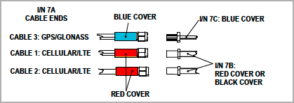
Connecting to Antenna Cables
Please refer to our knowledge base for further information on wiring and connections.
Replace an Existing Gateway
Remove power and serial connection terminal blocks, antennae connections, and any Ethernet or other cabling from the gateway to be replaced.
Remove existing gateway from enclosure and harness.
Replace existing gateway with new gateway by reconnecting the terminal blocks, antennae, cabling, and installing in the harness and enclosure.
Front Panel
The connections and ports located on the front panel of the equipment are described in this section.

Front Panel Connections and Ports
Descriptions for the port indicator lights as well as termination nodes are provided in this table.
Interface | Description |
PWR | Power Status LED |
WARN | Warning LED |
Status | Device Status LED |
NET | Cellular Network Connection LED |
Programmable 1 | Future use |
Programmable 2 | Future use |
Programmable 3 | Future use |
Programmable 4 | Future Use |
USER Button | Button to enable diagnostic features |
USB | USB Port |
ETH1 | Ethernet Connection vis Static IP |
ETH2 | Ethernet Connection via DHCP |
SD Card | Unused |
Reset | Tech support use only |
Left Panel
The connections and ports located on the left panel of the equipment are described in this section.
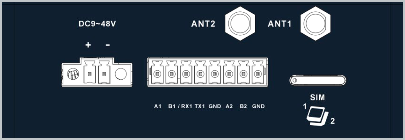
Left Panel Connections and Ports
Descriptions for the port indicator lights as well as termination nodes are provided in this table.
Interface | Description |
DC9-48V + | DC Power Positive |
DC9-48V - | DC Power Negative |
Ant2 | 4G/5G Diversity Antenna |
Ant1 | 4G/5G Primary Antenna |
A1 | Unused |
B1 | Unused |
RX1 | Serial RS-232 Receive |
TX1 | Serial RS-232 Transmit |
GND | Serial RS-232 Ground |
A2 | Serial RS-485+ |
B2 | Serial RS-485- |
GND | Serial RS-485 Ground |
SIM 1/2 | SIM Card slot (x2) |
Right Panel
The connections and ports located on the right panel of the equipment are described in this section.
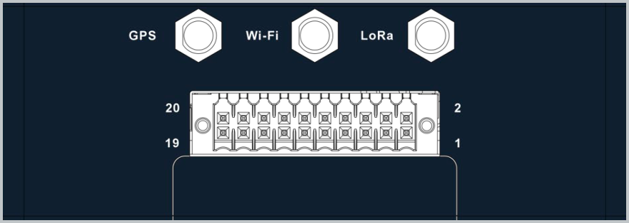
Right Panel Connections and Ports
Descriptions for the port indicator lights as well as termination nodes are provided in this table.
Interface | Description |
DC9-48V + | DC Power Positive |
DC9-48V - | DC Power Negative |
Ant2 | 4G/5G Diversity Antenna |
Ant1 | 4G/5G Primary Antenna |
A1 | Unused |
B1 | Unused |
RX1 | Serial RS-232 Receive |
TX1 | Serial RS-232 Transmit |
GND | Serial RS-232 Ground |
A2 | Serial RS-485+ |
B2 | Serial RS-48- |
GND | Serial RS-485 Ground |
SIM 1/2 | SIM Card slot (x2) |
If gateway power lights blink on the generator crank, this can indicate a brief loss of power to the gateway. To correct, ensure that power connections attach directly to the battery posts.
The gateway can support either positive or negative inputs for the “On” condition. If the orange wire is terminated to DC-, then the gateway will sense an “On” condition when input wires (Purple/Green/White/Yellow) have DC+ signal applied. If Orange wire is terminated to DC+, then the gateway will sense an “On” condition when input wires have DC- signal applied.
Troubleshooting
This section contains troubleshooting steps for a few common issues. For additional assistance, contact Generac Support at:
Phone: 1-888-234-3212
Help center and knowledge base: https://support.energyservices.generac.com/
Registered users: Support login
Issue 1: Site not reporting data: N/A shown in Values when streaming attempted
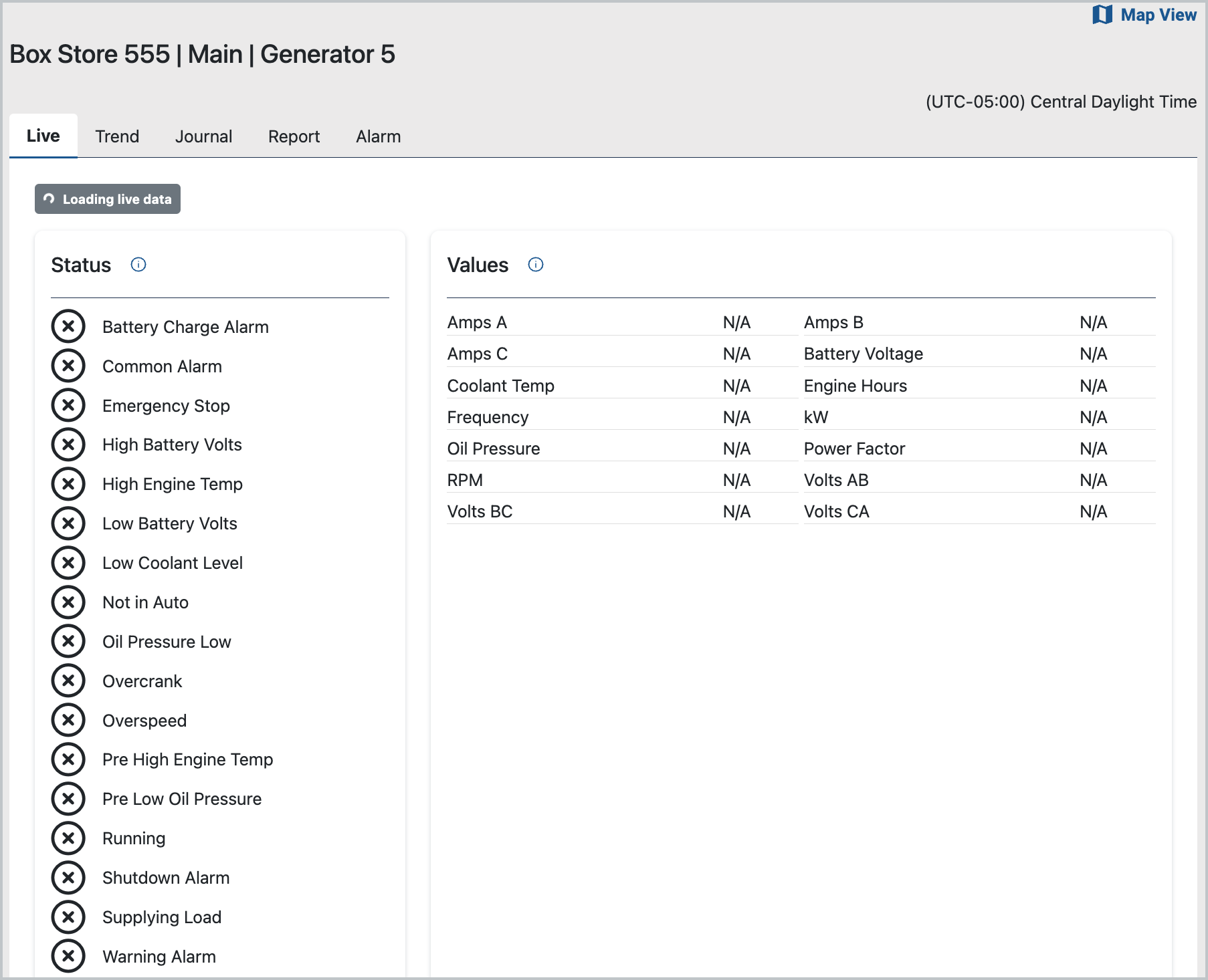
Possible Connectivity Issue
Root Cause
There is likely a Gateway to network connectivity issue.
Steps to Resolve
Confirm that the device is on by checking the PWR light, which should be illuminated and solid (without blinking).
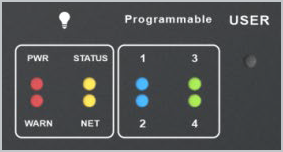
Power and Status Indicator Lights
If the PWR light is off, check red and black wire connections and voltage.
Confirm that the NET light is On. This light indicates if there is an active cellular connection and will blink while registering and illuminate (solid, without blinking) when connected. If NET light is off, confirm that antennae are firmly connected and move to the highest point possible.
The included antenna extension cables can be used to move the antenna to outside of the enclosure to improve the signal.
Cycle power to gateway by removing and re-inserting the inline harness fuse. Wait approximately one minute and check NET and signal lights again.
We also recommend that the onsite technician checks Verizon coverage at the site using Verizon’s coverage checker (https://www.verizon.com/coverage-map/). If necessary, determine if alternative carriers (AT&T / T-Mobile) have better reception in the area. Be sure to reach out to local site contacts.
If you are not able to resolve the issue, please contact Generac install support.
Issue 2: Site reporting -99 for data points
Cannot Establish Communication to Field Device
Root Cause
The Gateway is not able to establish Modbus or CANbus communication to field device(s).
Steps to Resolve
Programmable LEDs 1 (RS232), 2 (RS485), or 3 (CAN) will be illuminated (solid, without blinking) if there is an active connection to the device. If LEDs are off, check the gateway-side data cable connections on TB1 (OR/WH, WH/OR, BLU/WH).
Confirm proper wiring connections between the gateway and controller. Wiring information for Generac’s pre-installed generators is detailed in the table in this section and also available in the generator manual.
Confirm ethernet-connected devices are programmed with the correct IP address, as provided here.
Suggested IP settings:
IP Address: 192.168.3.2
Subnet Mask: 255.255.255.0
Default Gateway: 192.168.3.100If these steps do not resolve issue, contact Generac install support.
Gateway and Controller Connections
Power Wires (H-/G-Panel, PZPS, G8601) | Power Wires (Gemini) | Power Wires (IGNT) | RS232 Communication Wires (H-/G-Panel, IGNT) | RS232 Communication Wires (Gemini) | RS485 Communication Wires (PZPS, G8601) |
|---|---|---|---|---|---|
Wire #0: Black color (Negative) | Wire #0: Black color (Negative) | Wire #12: Black color (Negative) | Wire #387: Orange w/White Stripe color (RS232 RX) | Wire #387A: Orange w/White Stripe color (RS232 RX #1) | Wire #392: Orange w/White Stripe color (RS485 A) |
Wire #13/218: Red color (Positive, Pre-fuse) | Wire #13/218: Black color (Positive, Pre-fuse #1 & 2) | Wire #4: Red color (Positive, Pre-fuse) | Wire #388: White w/Orange Stripe color (RS232 TX) | Wire #388A: White w/Orange Stripe color (RS232 TX #1) | Wire #393: White w/Orange Strip color (RS485 B) |
Wire #15F/220F: Black color (Positive, Post-fuse) | Wire #15F/220F: Black color (Positive, Post-fuse #1) | Wire #4G: Black color (Positive, Post-fuse) | Wire #389: Blue color (RS232 COM) | Wire #389A: Blue color (RS232 COM #1) | Wire #COM: Blue color (RS485 COM) |
Wire #15G/220G: Black color (Positive, Post-fuse #2) | Wire #387B: Orange w/White Stripe color (RS232 RX #2) | ||||
Wire #388B: White w/Orange Stripe color (RS232 TX #2) | |||||
Wire #389B: Blue color (RS232 COM #2) |
Issue 3: Cannot log into platform
Steps to Resolve
If you know the email used to login, try resetting the password.
If you are not able to resolve issue, contact Generac support.
