
This topic guides technicians through the hardware components and troubleshooting details for the Factory Attached Advanced Gateway (GL899), installed on the models listed on this page.
The Advanced Gateway enables remote control and monitoring of backup power equipment leveraging Generac Link, our cloud solution for industrial IoT connectivity. This topic offers wiring and hardware details as well as some troubleshooting steps for a complete setup that enables continuous communications and remote access.
Advanced Gateway Commissioning
This topic details the hardware components and installation steps needed to commission an IoT-enabled generator and associated equipment.
Be sure to check out our FAQs for answers to common questions.
Tools Needed
Technicians should bring the following hardware and software to the installation.
On Hand
|
Hardware and Documentation
|
|
|
Access to Genlink software (specific to Generac controllers) |
|
|
Factory-attached harness details are available here. |
|
|
Modbus master simulator such as Modscan32 or Modscan64 |
|
|
Windows laptop with ethernet port |
|
|
Equipment controller documentation |
|
|
USB to RS485 converter |
|
|
USB to RS232 converter |
|
|
Ethernet (CAT5) cable |
|
|
Wireshark software installed on laptop—free download from internet |
|
|
Multimeter with AC/DC voltage, AC/DC current, and resistance measurement capability |
|
A0005681567 |
Hologram SIM Global IoT |
Components
Be sure to verify that the following hardware was included with the generator delivery.
Yes/No
|
Hardware
|
|
|
(1) GL899 Communication gateway (Generac part number: A0005495768) |
|
|
(1) 3-in-1 cellular and GPS antenna with pigtail |
|
|
(1) Verizon SIM card (activated and installed) |
|
|
Factory-installed communication and power harness |
Other checklist items for Site Deployment include verifying voltage and the condition of circuit fuses. Please follow the steps in this table.
Pass/Fail
|
Site Deployment Prerequisites
|
|
|
|
|
|
|
|
|
|
|
|
|
In the event that any of parts arrive damaged, please contact Support to open a ticket and request needed replacements.
Gateway Replacement Installations
If installing a gateway replacement, please follow these guidelines:
-
Power down gateway by removing inline harness fuse.
-
Remove all terminal blocks and antennae connected to the old gateway.
-
Remove gateway from enclosure or din rail mount.
-
Make note of the new gateway serial number.
-
Install new gateway in enclosure or din rail mount.
-
Reconnect all terminal blocks and antennae to new gateway.
-
Restore power to gateway by reinstalling inline harness fuse.
Powering Up Gateway
The necessary connections, inputs, and ports located on equipment panels are described in this section. Once the terminal blocks are connected to the gateway, the device may be powered on. To proceed:
-
Connect 7 pin terminal block to the gateway terminals labeled from 1 through 7
-
Insert the inline fuse to power up the gateway.
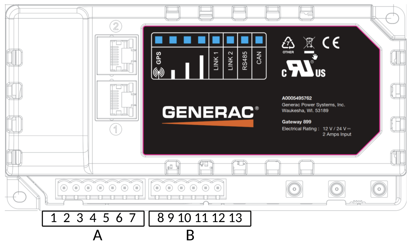
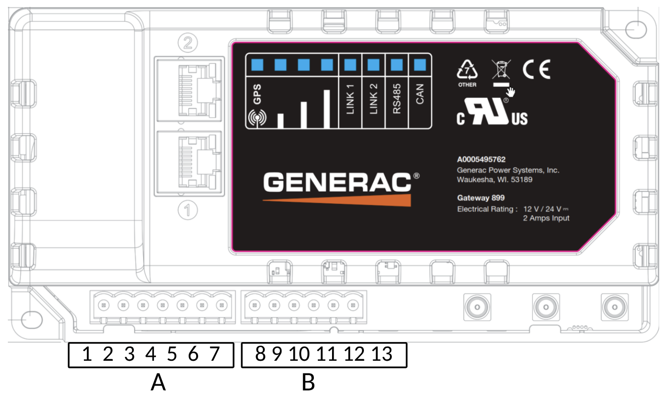
Descriptions for port indicator lights, inputs, and connections on the front panel are listed in this table.
LEDs
|
Description
|
|
GPS |
LED indicates if the gateway is connected to show current location of the gateway using GPS tracing. Also an indication whether gateway is receiving power or not
|
|
Signal Strength |
If all 3 lights are green, it means excellent cellular network available If 2 lights are green, it means satisfactory cellular network available If 1 light is green or all are off, it means poor cellular network available |
|
LINK1 |
GREEN: Means the gateway has connection to IOT cloud RED: Means the gateway is trying to negotiate connections with IOT cloud |
|
LINK2 |
NOT USED |
|
RS485 |
Solid GREEN means gateway has established good connection via Modbus RS485 with the field controller Blinking green means gateway has lost connection with field controller via RS485 |
|
CAN |
Fast blinking green means gateway is communicating over CANBus network Off means gateway is not communication via CANBus network |
|
ETH1 |
Ethernet Connection via static IP |
|
ETH2 |
Ethernet Connection via DHCP |
Descriptions for ports and terminations on the gateway are listed in this table.
Terminals/ Ports
|
Description
|
|
1 |
DC Power Negative |
|
2 |
DC Power Positive |
|
GPS |
GPS Antenna port (Blue) |
|
Main |
Cellular antenna port (Red) |
|
Diversity |
Cellular antenna port (Blue) |
|
3 |
Digital Output 1 |
|
4 |
Digital Output 2 |
|
5 |
Digital Output Common |
|
6 |
Analog Input 1 (0-10vdc) |
|
7 |
Analog Input 2 (0-10 vdc) |
|
8 |
Serial RS-485+ |
|
9 |
Serial RS-485- |
|
10 |
Serial RS-485 GND |
|
11 |
CAN_H |
|
12 |
CAN_L |
|
13 |
CAN_GND |
Some factory-attached connectivity gateways initially shipped with the cellular antenna disconnected from the gateway. The issue has been corrected for new shipments. For existing inventory, please confirm that the pigtails coming from the gateway enclosure are connected to the antenna cables as illustrated in the following diagram (Red > Red/Black and Blue > Blue). This will ensure the gateway has adequate cellular signal strength to communicate with the connectivity platform.
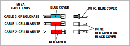
Please refer to our knowledge base for further information on wiring and connections.
Troubleshooting
Check this section to resolve any issues experienced while setting up the Advanced Gateway.
Verifying Proper SIM Installation
-
Power off the gateway.
-
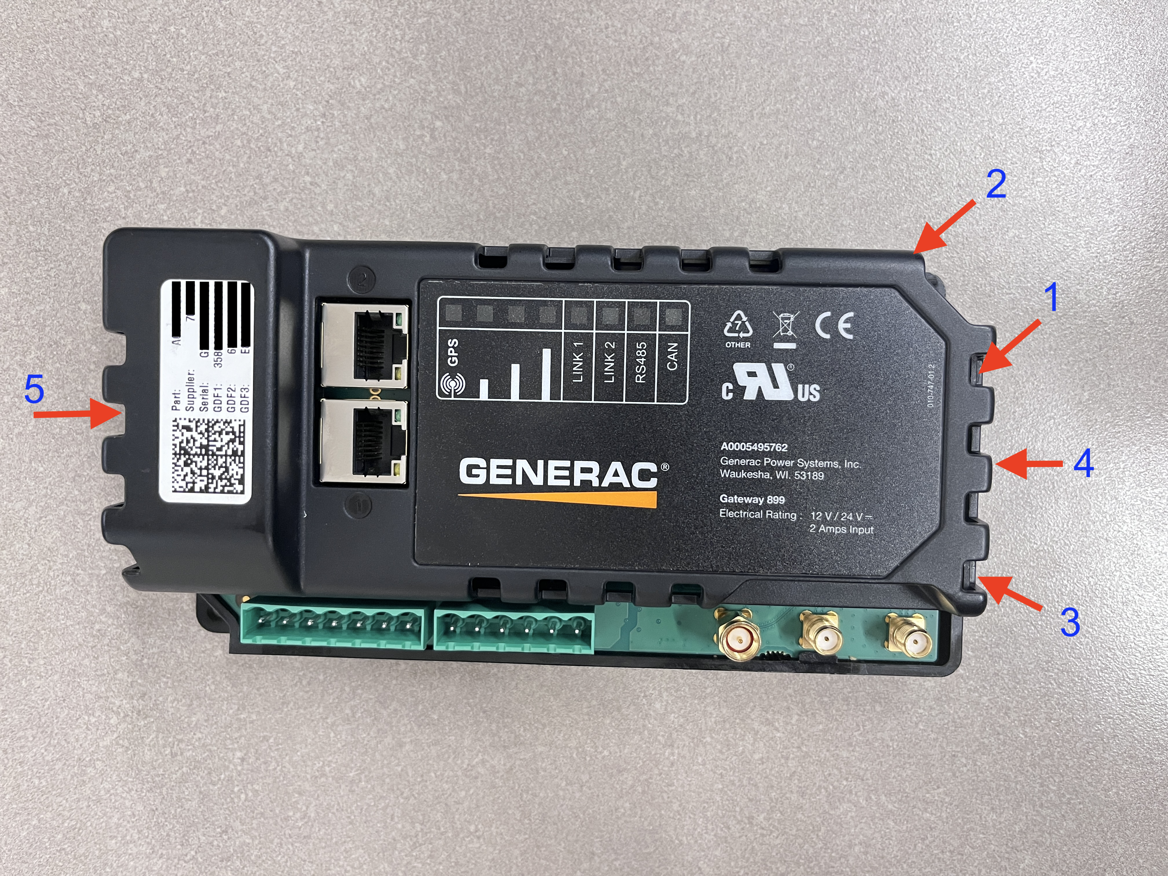
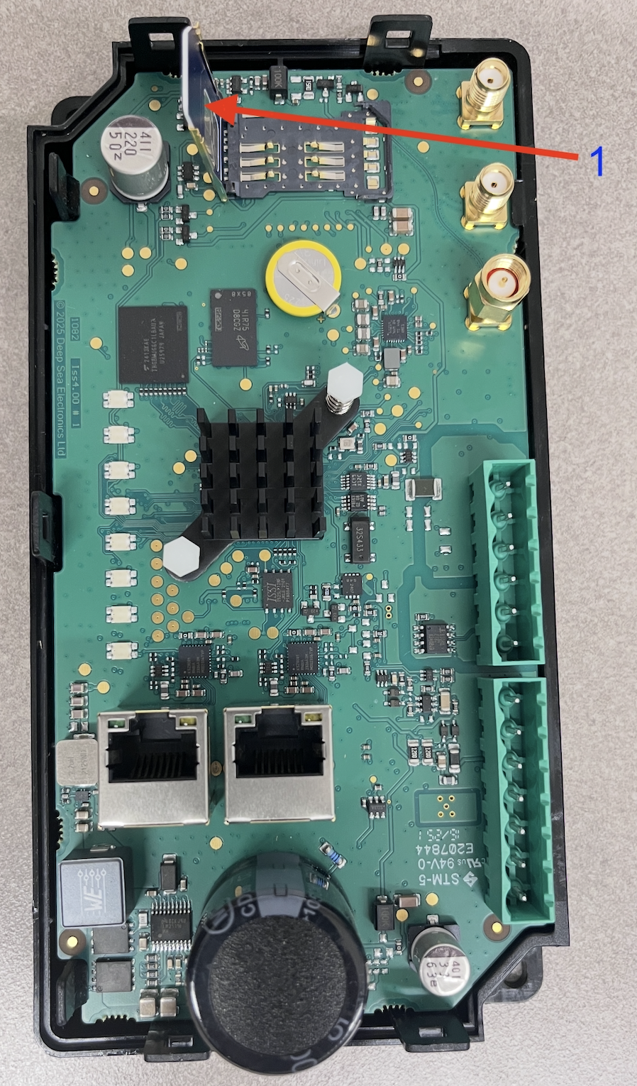
To open the SIM card slot, check the image below and follow the procedure given here
-
#1 - Insert a flat head screw driver and push the notch back
-
#2 - At this time pull the top cover
-
#3 - Next push the notch with flat head screw driver
-
#4 - Pull up the cover
-
#5 - Pull up the other end of cover
-
-
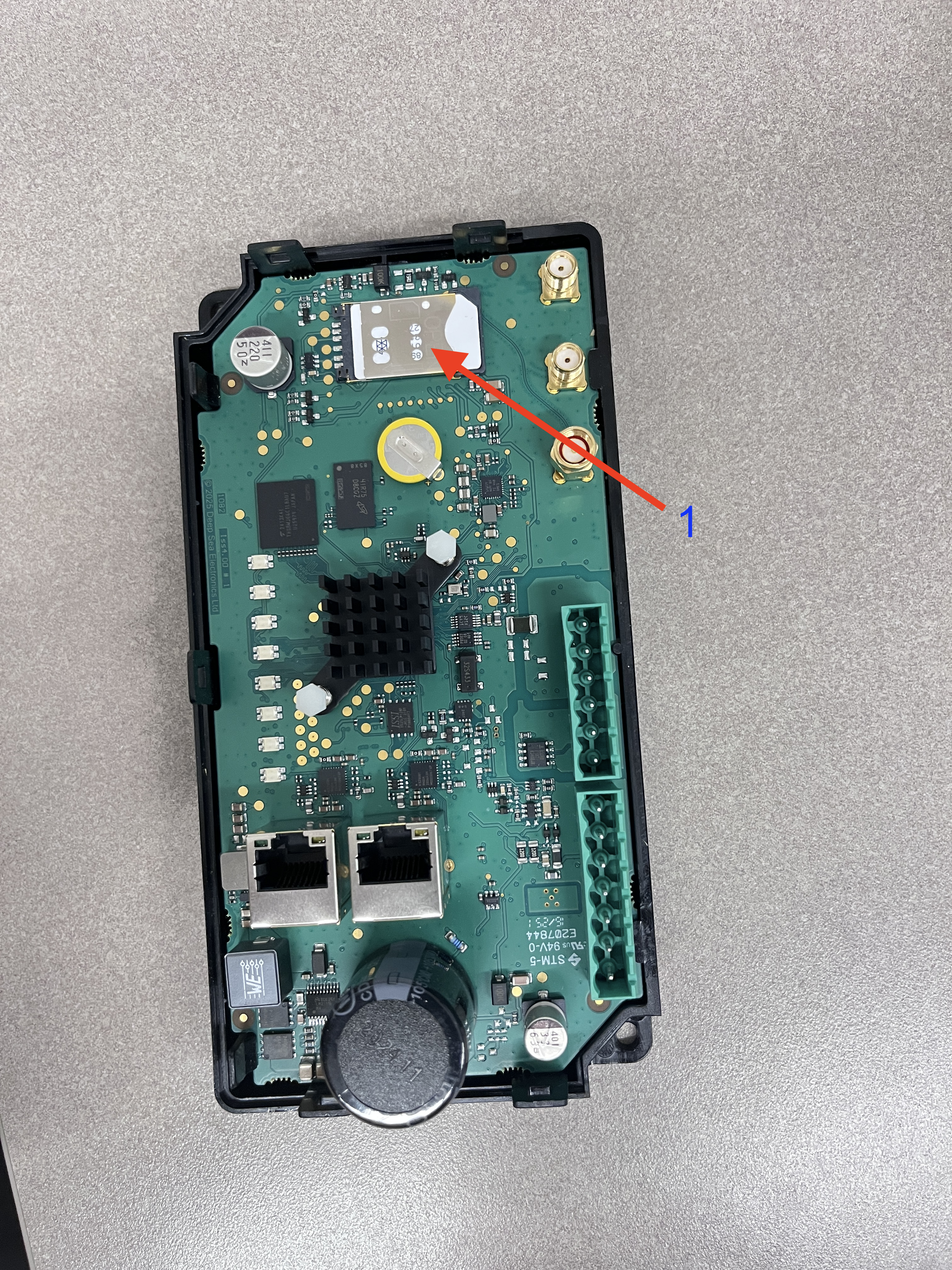
Verify that the SIM card on arrival is inserted in the slot, as depicted in the photo, with chip wiring facing down.
-
To replace the SIM or insert a new one, push the SIM cover back with thumb away from antenna terminals. Then insert the SIM in the slot, close the cover and push the cover back towards antenna terminals.
Using a LAN-Based Internet Connection
For LAN wired internet connectivity, ports 443, 5671, and 8883 must be opened for outbound traffic on the facility firewall, if applicable. The customer-provided Ethernet connection must be configured to assign the Generac Link gateway an IP address via DHCP and connected to port 2.
-
Run network cable from customer’s nearest network infrastructure to a laptop.
-
Verify that the network cable has an active internet connection by opening a web browser and attempting to access http://www.google.com .
-
If laptop test is successful, connect Ethernet cable to port 2 on the gateway. If test is not successful work with facility IT to resolve.
-
Power off the gateway.
-
Remove SIM card(s) from the gateway.
-
Power on the gateway.
-
Wait 10–15 minutes then check the Generac Link Manager for live data streaming. If it is not communicating, please reach out to Support.
A computer based call using Microsoft Teams may be needed to share your screen with on of our solutions engineers.
Changing Communication Option from Serial to Ethernet
-
Enable the Modbus TCP port on the controller.
-
Set the controller IP address in 192.168.3.x (that is, any value with the exception of 192.168.3.100).
-
Set subnet mask to 255.255.255.0.
-
Run ethernet cable and connect to generator controller Modbus TCP port as well as ETH1 port on Generac Link gateway.
-
Contact Support to reconfigure site for Modbus TCP communications.
-
If controller IP address cannot be changed due to site restrictions, please reach out to schedule a session with a Solutions Engineer.
-
If the technician does not have password to change communication setup on controller, reach out to the IDC master tech or to the generator support team.
-
If the technician does not know where to change the communication setup, reach out to the IDC master tech or generator support team.
Replacing an Existing Gateway
-
Remove both terminal blocks terminal blocks, antennae connections, and any Ethernet or other cabling from the gateway to be replaced.
-
Remove existing gateway from enclosure.
-
Replace existing gateway with new gateway by reconnecting the terminal blocks, antennae, cabling, and installing in the harness and enclosure.
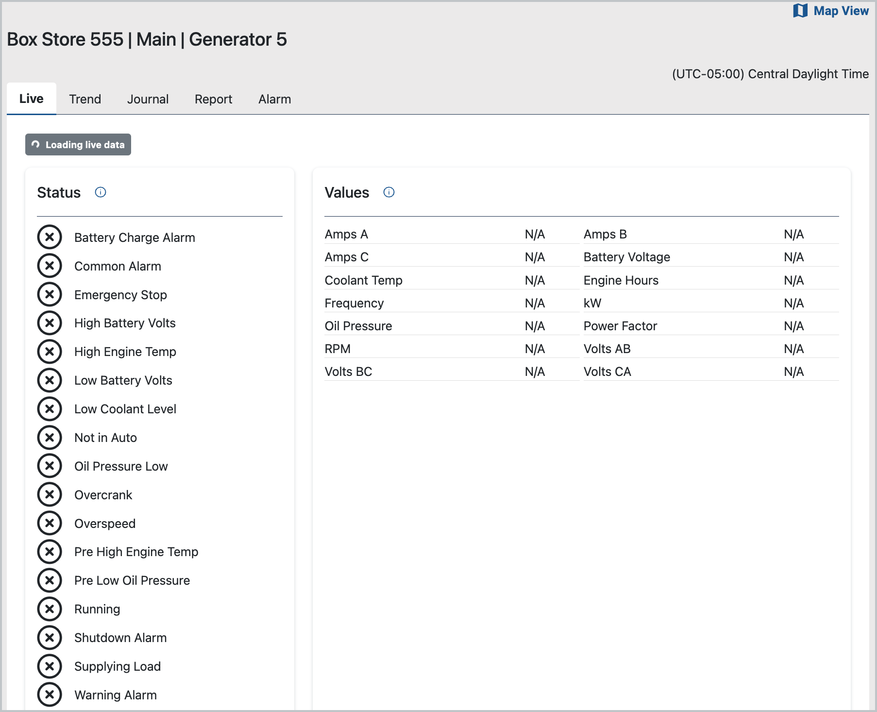
Data Values of N/A
There may be a gateway-to-network connectivity issue.
Steps to Resolve
-
Confirm that the device is on by checking GPS light, which should be illuminated and solid RED.
-
If all the lights are off, check red and black wire connections and voltage.
-
Confirm that at least two cellular signal bar lights are On.
-
Confirm that LINK1 light is solid green. If it remains red 15 minutes after gateway power up, there is no active cellular connection or gateway is not able to register with IOT cloud. Confirm that antennae are firmly connected and move to a location with the best possible signal.
The included antenna extension cables can be used to move the antenna outside of the enclosure to improve the signal. Make sure the antennae connected to GPS, Main and Diversity are mounted to a place of maximum cellular coverage.
-
Cycle power to gateway by removing and re-inserting the inline harness fuse. Wait approximately five-ten minute and check the ights again.
-
We also recommend that the onsite technician checks Verizon coverage at the site using Verizon’s coverage checker (https://www.verizon.com/coverage-map/). If necessary, determine if alternative carriers (for example, AT&T or T-Mobile) have better reception in the area. Be sure to reach out to local site contacts.
Values of -99 Populate Data Stream
A value of -99 indicates a Modbus serial communications issue.
To resolve this issue, be sure to take the following steps:
-
Check and compare the settings for the following with the controller-specific installation instructions.
RS232 Settings
-
Baud rate
-
Parity
-
Modbus address
For the DB9, be sure to disconnect then reconnect.
Modbus RS485 Settings
-
Baud rate
-
Parity
-
Modbus address
Modbus TCP Settings
-
IP Address: 192.168.3.2
-
Subnet Mask: 255.255.255.0
-
Default Gateway: 192.168.3.100
-
Confirm proper wiring connections between the gateway and controller.
-
Power cycle the equipment controller.
Be sure firmware version on PowerZone Pro Sync is 1.23.2 or higher.
Gateway and Controller Connections
Wiring for the gateway and controller panels are summarized in this table. Be sure to also refer to the Wiring and Harness diagrams.
Power Wires (PZPS, G8601)
|
RS485 Communication Wires (G8601)
|
Modbus TCP (PZPS)
|
|---|---|---|
|
Wire #0: Black color (Negative) |
Wire #392: Orange w/White Stripe color (RS485 A) |
Ethernet network cable from Eth1 on gateway to PZPS display |
|
Wire #13/218: Red color (Positive, Pre-fuse) |
Wire #393: White w/Orange Strip color (RS485 B) |
|
|
Wire #15F/220F: Black color (Positive, Post-fuse) |
Wire #COM: Blue color (RS485 COM) |
|
For needs requiring immediate assistance, contact Generac Support at:
-
Help center and knowledge base: https://support.energyservices.generac.com/
-
Registered users: Support login