
After-Market Kit Installation and Troubleshooting Guide (Version 2)
The latest Aftermarket Gateway kit (G0097460) and universal harness (A0006648426) enables remote control and monitoring of backup power equipment leveraging Generac Link Manager, our cloud solution for industrial IoT connectivity. This topic offers wiring and hardware details as well as some troubleshooting steps for a complete setup that enables continuous communications and remote access.
Commissioning the Gateway
This topic details the hardware components and installation steps needed to commission an IoT-enabled generator and associated equipment.
Be sure to check out our FAQs for answers to common questions.
Tools Needed
Technicians should bring the following hardware and software to the installation.
On Hand | Hardware and Documentation |
Access to Genlink software (specific to Generac controllers) | |
Modbus master simulator such as Modscan64 | |
Windows Laptop | |
USB to serial connector |
Kit Components
For first-time installs, verify that the following hardware is included with the kit.
The after-market Gateway has four antennae ports: GPS, Wi-Fi, as well as ANT1 and ANT2 for cellular connectivity.
Included with Kit Packaging | Hardware included with Gateway |
(1) Communication gateway (Inhands Device) | |
(1) Ethernet network cable | |
(2) Cellular antennae | |
(1) Verizon SIM card (activated and installed) | |
(1) GPS antenna | |
(1) 120VAC power supply (not required for typical installation) | |
(1) Wifi antenna (not required for typical installation) | |
(2) Mounting brackets with attached magnets |
Included with Kit Packaging | Hardware included with Harness |
(1) Easy connect harness | |
(2) 24VDC relays | |
(1) RS232 comm port breakout board and cover | |
(1) four-position terminal block for Generac Power Zone Gateway RS485 terminal block | |
(1) four-position terminal block for Generac Power Zone Pro Sync Display RS485 port |
Other checklist items for Site Deployment include verifying voltage and the condition of circuit fuses. Please follow the steps in this table.
Pass/Fail | Site Deployment Prerequisites |
| |
| |
| |
|
Installation Steps
The remaining steps needed for a complete installation are provided in this section, which details kit components.
Identify components included in the kit as provided in the previous section.
In the event that any of these parts arrive damaged, please contact Support to open a ticket and request needed replacements.
Identify existing din rail or space for magnet mounting of gateway. Gateway should be mounted in interior of gen controller enclosure where possible to limit vibration and weather exposure.
Connect included cell antennae to AN1 and ANT2 ports on side of the gateway. Mount as close to outside of generator enclosure as possible. Antennae ends should be separated approximately 12”-18”. Installation of a drip loop is required to keep water from entering unit.
Connect included GPS antenna to GPS port on side of gateway. Mount as close to outside of generator enclosure as possible. Installation of a drip loop is required to keep water from entering unit.
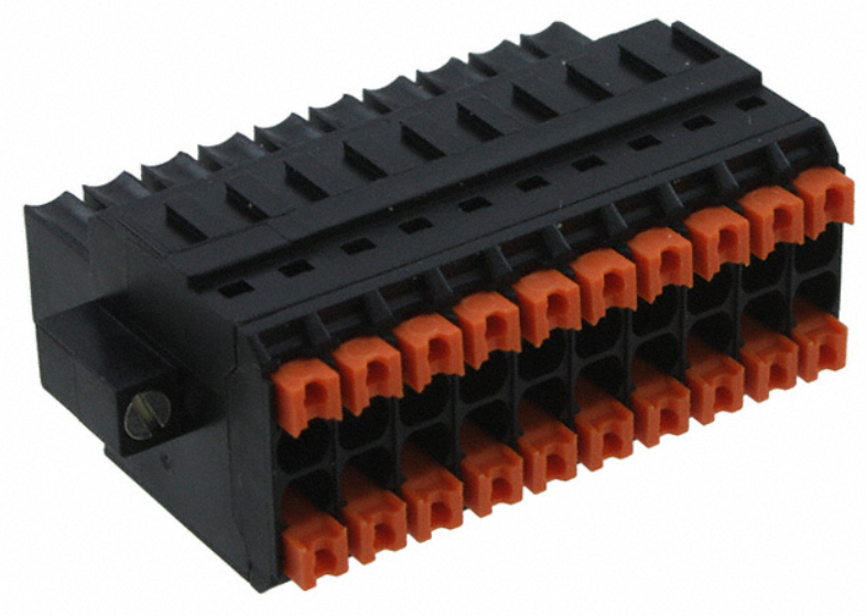
Inspect wiring harness and identify customer and gateway ends. Gateway end will have 3 pre-wired terminal blocks (2 green and 1 black).
Route customer end to be near generator termination points. See generator controller specific reference pages for recommended terminations.
Make final connections on customer end per documentation.
Connect pre-wired 20 pin black terminal block to connector on right side panel of gateway that has GPS and Wi-Fi antenna posts.
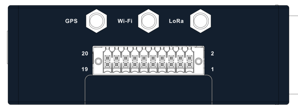
Right Panel
Right Panel Harness Connector
Connect 8 pin and 2 pin terminal block to left panel side of gateway.
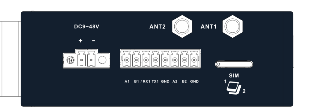
Left Panel
If included ethernet cable is being used for modbus communication to equipment, connect to the ETH1 port on front of gateway.
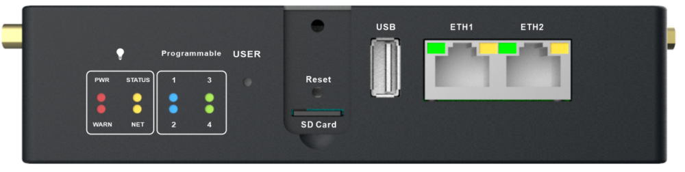
Use ETH1 for Modbus TCP connections (Front Panel)
External device will need to be programmed with like IP address for communication to be established.
Default ETH1 Port Settings: | Recommended Equipment |
|---|---|
IP Address: 192.168.3.100 | IP Address: 192.168.3.2 |
If default or recommended settings can not be used contact customer support.
Wire Termination Setup Detail
The table below outlines each connection for the advanced aftermarket gateway and universal harness, detailing how they interface with the equipment to be monitored.
We recommend scheduling time with a Generac solutions engineer before attempting to connect multiple assets through one gateway. For example, if your site hosts multiple generators, ATSs, or fuel sensors, more advanced support may be required to communicate via one gateway.
Generac Gateway Side Termination | Description | Universal Harness Wire Color | Customer Side Terminations |
+ | DC+ | Red | Battery(+) |
- | DC- | Black | Battery(-) |
A1 | NOT USED | ||
B1 | NOT USED | ||
RX1 | RS232 Data Receive | White/Orange | RS232 Transmit (3-TXD) |
TX1 | RS232 Data Transmit | Orange/White | RS232 Receive (2-RXD) |
GND | Data Ground | Green/White | RS232 GND (5-GND) |
A2 | RS485 Modbus + | Blue/White | RS485+ |
B2 | RS485 Modbus - | White/Blue | RS485- |
GND | RS485 Modbus GND | White/Green | RS485 GND |
1 | Analog Input + | Red/Black | Analog Input + (4-20mA)* |
15 | Digital Input 1 | Purple | Engine Running** |
16 | Digital Input 2 | Green | Not in Auto** |
17 | Digital Input 3 | White | Common Alarm** |
18 | Digital Input 4 | Yellow | Spare Input** |
Harness Relay #1 | COM | Blue | 2-Wire Gen Start |
N/O | White / Blue | ||
N/C | Blue / White | ||
Harness Relay #2 | COM | Brown | Spare Output |
N/O | Green / Yellow | ||
N/C | White / Orange | ||
*The 4-20mA sensor should use the same DC+ source as the gateway. The sensor's signal/output connects to the red/black wire of the harness.
**Digital inputs require a DC+ signal for activation. The DC wetting voltage should correspond to the gateway's DC+ source..
Troubleshooting
Check this section to resolve any issues experienced while setting up the Advanced Gateway.
Front Panel Indicators and Components
Front Panel Component | Description |
PWR | LED indicates power to the Gateway:
|
WARN | On or blinking indicates an error condition. Off indicates normal activity. |
STATUS | LED indicates device status:
|
NET | LED indicates if there is an active cellular connection:
|
Programmable 1 | Future use |
Programmable 2 | Future use |
Programmable 3 | Future use |
Programmable 4 | Future Use |
USER Button | Button to enable diagnostic features (for future use) |
USB | USB Port |
ETH1 | Ethernet Connection via static IP |
ETH2 | Ethernet Connection via DHCP |
SD Card | Unused |
Reset | Tech support use only |
Verifying Proper SIM Installation
Power off the gateway.
To open the SIM card slot, a paper clip needs to be inserted in small hole located on card holder. Hole can be seen toward edge of extended holder in picture provided.
Verify that the SIM card on arrival is inserted in the primary slot, as depicted in the photo, with chip wiring facing up. A backup slot (as part of the same tray) is available for a Hologram SIM card. If specifically requested to do so by Support, insert the SIM into the second position with chip wiring facing down.
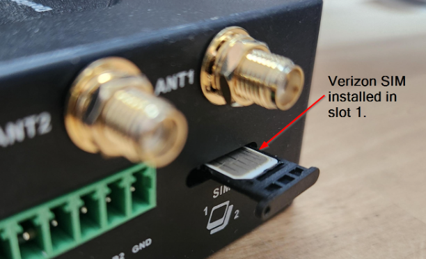
SIM Tray on Left Panel
If the NET LED continues to blink for more than 15 minutes, ensure that the antenna is properly connected. In addition to this topic, please refer to our FAQs for additional workflows.
Using a LAN-Based Internet Connection
For LAN wired internet connectivity, ports 443, 5671, and 8883 must be open for outbound traffic on the facility firewall, if applicable. The customer-provided Ethernet connection must be configured to assign the Generac Link gateway an IP address via DHCP.
Run network cable from customer’s nearest network infrastructure to a laptop.
Verify that the network cable has an active internet connection by opening a web browser and attempting to access http://www.google.com .
If laptop test is successful, connect Ethernet cable to ETH2 port on the gateway. If test is not successful work with facility IT to resolve.
Power off the gateway.
Remove SIM card(s) from the gateway.
Power on the gateway.
Wait 10–15 minutes then check the Generac Link Manager for live data streaming. If it is not communicating, please reach out to Support.
A computer based call using Microsoft Teams may be needed to share your screen with on of our solutions engineers.
Changing Communication Option from Serial to Ethernet
Enable the Modbus TCP port on the asset controller.
Set the controller IP address in 192.168.3.x (any value, with the exception of 192.168.3.100).
Set subnet mask to 255.255.255.0.
Run ethernet cable and connect to asset controller Modbus TCP port as well as ETH1 port on Generac Link gateway.
Contact Support to reconfigure site for Modbus TCP communications.
If controller IP address cannot be changed due to site restrictions, please reach out to a Solutions Engineer.
If the technician does not have password to change communication setup on controller, reach out to the IDC master tech or to the generator support team.
If the technician does not know where to change the communication setup, reach out to the IDC master tech or generator support team.
Data Values of N/A
A connectivity issue may exist between the gateway and the network.
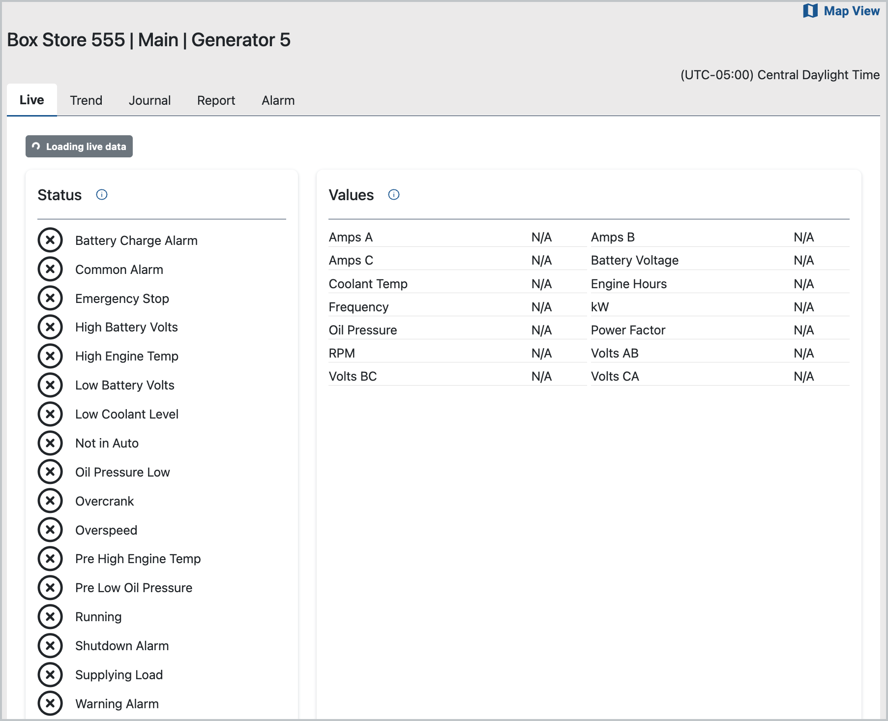
Possible Connectivity Issue
Steps to resolve
Confirm that the device is on by checking PWR light is solid red.
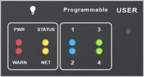
Gateway LED indicator on front panel
If PWR light is Off, check voltage at + and - terminals.
To verify the gateway's cellular connection, check the NET light. A solid light indicates an active connection. If the NET light is blinking continuously, try the following steps to resolve the issue.
Ensure both antennas are securely connected to the ANT1 and ANT2 ports on the gateway and positioned to maximize cellular signal strength. After confirmed, reboot gateway.
Verify Verizon coverage using Verizon’s coverage checker.(https://www.verizon.com/coverage-map/). If needed, check whether alternative carriers (such as AT&T or T-Mobile) provide better reception. We recommend consulting local site contacts for assistance.
If the above are verified OK and the application still indicates N/A in the data stream, please contact Support.
Values of -99 Populate Data Stream
A value of -99.0 indicates a Modbus communications issue.
To resolve this issue, take the following steps:
Verify that the asset communication port settings align with the specifications in the controller-specific installation instructions.
For RS232 connections utilizing included DB9 adapter, try disconnecting and then reconnecting to asset comm port.
Be sure firmware version of Power Zone Pro Sync is 1.23.2 or higher.
Confirm proper wiring connections between the gateway and controller.
Power cycle the equipment controller.
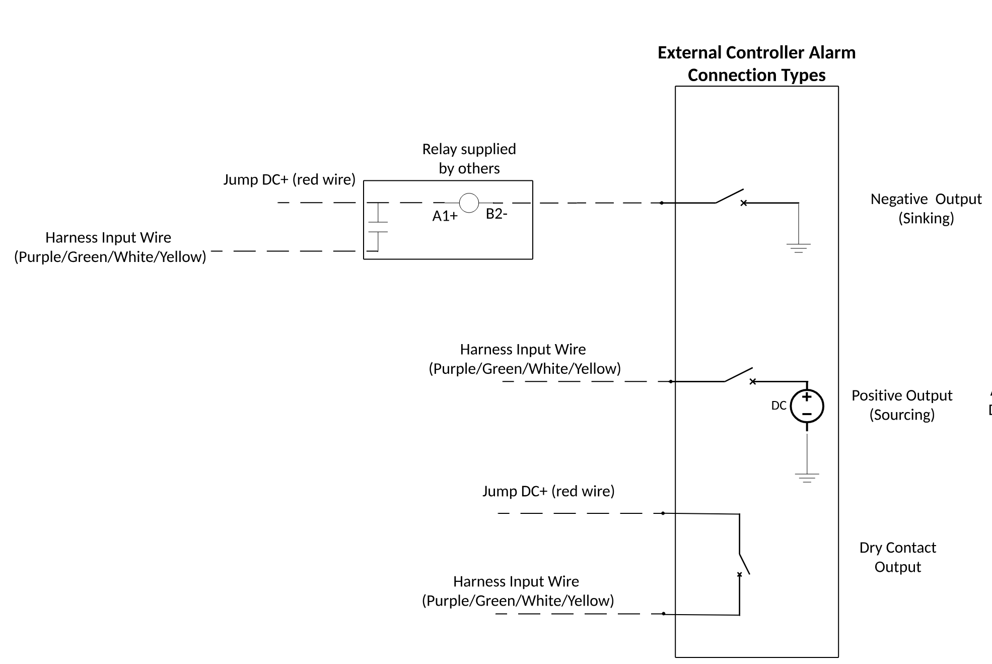
One or More Hardwired Digital Input Statuses Are Not Showing Correctly
Confirm black wire is landed securely at right panel connector, terminal 4.
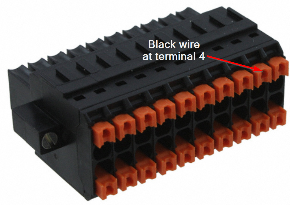
Right panel connector - location of digital input common
Ensure the corresponding input wire has DC+ present and is common to the DC+ at the gateway harness red wire.
Note that it is not possible to use any of the inputs of this aftermarket gateway as sourcing inputs meaning DC+ sourced by the input to a sinking contact.
Option#1 (using external relay) in the snippet below can be used to connect an input
One or Both Relays on Wire Harness Not Functioning
Command to trigger on/off from platform is failing
Make sure there are no –99 values shown on the platform for the equipment under consideration.
Listen for click sound when a particular output is triggered on/off from platform.
Sound may become overwhelmed/masked by the noise of other equipment.
Connect a multi-meter in continuity measurement mode between Blue and White/Blue wires for checking relay #1 or Brown and Green/ Yellow wires for checking relay #2.
Be sure to disconnect wires from the controller, which must be absent any voltage before testing. When the output is initiated from the platform, relay contacts should close and when turned off, the contacts should open.
If the above steps do not resolve the issue, the harness may need to be replaced. To do so, place an order using part number A0006648426 by submitting a Support ticket. Once the new harness arrives, follow these steps again.