
Generac Power Zone 410 Controller
This topic is the install guide for the after-market gateway (part# G0097460) with the universal harness (part# A0006648426) utilizing the Generac PowerZone® 410 Controller.
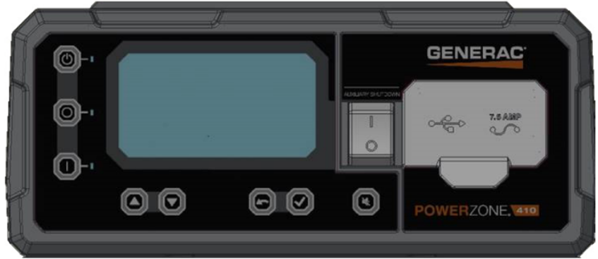
Generac Power Zone 410 Controller Display
Power Zone 410 Wiring and Connections
Modbus Communication Settings and Notes
Settings should correspond to the values provided in this table.
Address: 157 | Data Bit: 8 |
Baud Rate: 9600 | Stop Bit: 1 |
Parity: None | |
If different settings are required, please contact Support.
From the control panel as depicted in the schematic in this section, follow the steps provided here.
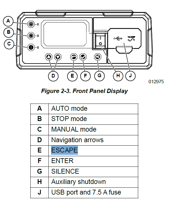
Front Panel Display
RS485 slave port configuration can be reached through Dealer Menu by entering the Dealer Code.
Edit Settings>Config RS485 Slave.
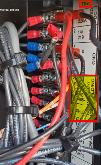
Equipment Connection Details
Generac Gateway Side Terminations | Description | Harness Wire Color | Equipment Side Terminations |
|---|---|---|---|
+ | DC+ | Red | B+ |
- | DC- | Black | B- |
A2 | Data + | Blue / White | TB2—RS485+ |
B2 | Data - | White / Blue | TB2—RS485- |
GND | Data GND | White / Green | TB2—SHLD |
Harness Relay #1 | COM | Blue | 2-Wire Start |
N/O | White / Blue |
Gateway Connection Ports
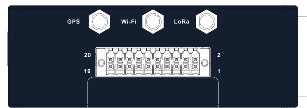
Gateway Right Panel—GPS antenna and harness I/O connections
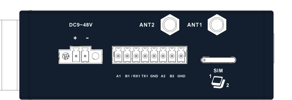
Gateway Left Panel—Cellular antenna, power, serial communication ports, and SIM card slot
Check out our knowledge base and support center for information on any technical questions.